Nothing else should need replacing.
Ok. I guess I'll know for sure once I do some more tests. I just figured the volume pot might need it since the amp is from 83-84.
It's ok to run it without the STK although the large PSU caps may hold a charge for some time, make sure they are discharged before doing any soldering or desoldering, short them with a large value (~20K) resistor if necessary.
Good to know! Thanks. I'll do just that.
Does the relay operate with the STK removed?
I actually haven't powered it since I wanted to know if it was safe to do so. I'll try it later and let you know.
I did have a question though. I've read on here about the advantages of replacing the large caps with several in parallel. With this amp, the two large caps used are 8200uF (56V). Would it be safe to go higher?
So for example, 3 caps @ 4200uf (60 -64V) for each rail?
That small increase in capacitance shouldn't be a problem, there might be a slight increase in surge current as they charge which may blow the mains fuse if it's close rated
I figured something might give if there's too much of an increase (I was thinking mainly the rectifier or transformer). Part of the reason I'm asking is because I have a Yamaha amp (RX-V490 which works fine) which has the same reservoir caps. If I'm going to order, I would do them both.
Edit: Also ordering an ESR meter.

Hey. Just an update:
With the STK removed, the amp's relay now clicks (takes about 3 seconds from turn on). So that's great news.
I've gone ahead and ordered a pair of pulled replacement STK 4893s and ordered new capacitors. I'm just going to use one per rail.
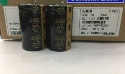
63v, 10,000uf. (see attached pic).
With the STK removed, the amp's relay now clicks (takes about 3 seconds from turn on). So that's great news.
I've gone ahead and ordered a pair of pulled replacement STK 4893s and ordered new capacitors. I'm just going to use one per rail.
63v, 10,000uf. (see attached pic).
Attachments
The relay functioning is good news. Those caps will be fine so long as they fit
Got the ESR meter today. Tested the old caps still in circuit (I know it's best to test removed from circuit and will do so while making sure I test at room temp to compare).
Tested each of the 2 about 10 times. Reason being, kept getting 2 approximate results.
Capacitor A:
Vloss 1.3%
8763uF
ESR read 0.45Ω a few times.
The rest of the time it read 1.4Ω
Capacitor B:
Vloss 1.6%
8981uF
ESR read 0.42Ω a few times.
The rest of the time it read 1.5Ω
I believe if they were new, the ESR of these would have been 0.10Ω-0.12Ω max.
Will definitely remove them and test again. But assuming the lowest values I read were correct, that would still indicate bad caps. Given their age (30+ years), it's guaranteed. Just speaking from a measurement perspective.
Edit: I almost forgot: The 2 pulled STK ICs came in. Would it be really unwise to solder one and do a quick test first? I ask, because I've read that sometimes people installed a replacement STK and immediately fried (likely due to something else in the circuitry being greatly off spec, or possibly due to an incompatible revision of an IC being substituted). My feeling is that it'd be risky without replacing all the caps first and testing the voltages across the circuit.
Last edited:
How do you mean "all the caps"? I thought you were just going to replace the two smoothing caps.
So long as the supply voltages are correct you can solder in the STK
I was thinking of replacing all the amp board electrolytics with new ones of the same value. I read that was recommended in order to prevent oscillation and frying the amp again.
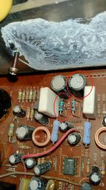
I'm just in the middle of doing further testing and so far found a bad capacitor and resistor where the STK was (circled in red in the attached pic). The cooked resistor is pretty much in line where the burnt transistor was in the STK.
This resistor would not read on my DMM. I inspected it closely and noticed a burn mark on it. I looked up the color code bands, but cannot understand what the 5th white band signifies. The colors appear to me as being: Green, Blue, Brown, Red and White. Do you know what this value is?
The Capacitor doesn't want to read on my ESR meter. Out of 10 tries, it might read as a diode a couple of times, other than that the meter says unknown or damaged. So I think it's safe to say that it's gone bad.
Attachments
Last edited:
It's "FR1" a kind of fuse, have a look for it in the circuit diagram, it's in the negative supply to pin 6, it's in the parts list at the end, see if you can find anything out about it by doing a search using the part number. I'm going to be busy for a few hours now, good luck
It's "FR1" a kind of fuse, have a look for it in the circuit diagram, it's in the negative supply to pin 6, it's in the parts list at the end, see if you can find anything out about it by doing a search using the part number. I'm going to be busy for a few hours now, good luck
Yes. On the circuit board, it's connected to the negative supply from the neighboring capacitor, and connects between pin 6 and pin 7 of the STK.
Ref# 2-FR1, Part# ER-349423
It's spec'd in the service manual as:
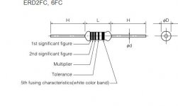
R FUSE ERD2FC S10 1/4W 5600G
I didn't find anything online based on the reference number or part number. I was able to pull up 1/4W ERD2FC resistor fuses. Just need to determine what S10 and 5600G signify before I source a suitable replacement. I will continue to research this. Thanks.
So I read the Panasonic Data Sheet and read specs and color bands:
It's a 1/4 Watt, 560 ohm fusible resistor.
Since finding these are quite difficult, could I substitute this with a 2w or 3w 560Ω metal film resistor?
It's a 1/4 Watt, 560 ohm fusible resistor.
Power Rating at 70 degrees Celsius: 0.25W
Fusing characteristic: Shall fuse within 60 s at over 2.25 W load
Since finding these are quite difficult, could I substitute this with a 2w or 3w 560Ω metal film resistor?
Attachments
Last edited:
Just an update:
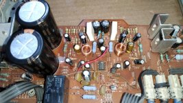
I've soldered in the replacement reservoir caps and replaced a few other capacitors nearby where the STK should go.
The relay was mostly turning on before (probably 7 out 10 tries), but now not at all. So I measured the voltage on pins 3 and 6 against the negative speaker terminal. I'm getting -48v on both pins. Not sure why.
The old reservoir caps pulled had 3 pins on each, but I believe the 3rd was a dummy pin, which was on the same traces as the capacitor's negative pins. The board itself, had alternate holes for the pin spacing used on on my Elna caps. They fit perfectly and are soldered in the same polar orientation (capacitor negative marking soldered on board's negative marking). All the caps replaced are installed correctly too and tested fine for polarity between neighboring pins of the same traces. So I'm not sure whats up.
Edit: Ok, so this is weird. If I turn off the amp and turn it on immediately, the relay clicks... So now I'm thinking on of the other caps I haven't replaced is far below it's value?
Attachments
Last edited:
Attached is the data sheet on the chip used in the protection circuit. Been reading the voltages from the different pins but not quite sure how to isolate the intermittent relay problem.
If I turn on the amp without the relay engaging, these are the values I'm reading:
Pin 1: 2.8mv
Pin 2: -0.18v
Pin 3: 0.8v
Pin 4: 2.44v
Pin 5: GND
Pin 6: 43v
Pin 7: 0.03v (this number begins climbing up to 1.5v~, but then drops off if the relay doesn't engage)
Pin 8: 3.44v
If I turn it off and back on within 10 seconds, the relay will engage a few seconds later and these are the values I read from the pins:
Pin 1: 8.9mv
Pin 2: -0.15v
Pin 3: 0.23v
Pin 4: 2.52v
Pin 5: GND
Pin 6: 0.77v
Pin 7: 2.26v
Pin 8: 3.46v
I'm not sure of the absent STK IC is the reason for it being intermittent.
Attachments
Last edited:
- Status
- This old topic is closed. If you want to reopen this topic, contact a moderator using the "Report Post" button.
- Home
- Amplifiers
- Power Supplies
- Transformer Newbie Question