Hello resourceful people of diyaudio, My knowledge is somewhat mediocre, might be easy solution for some of you, so here we go:
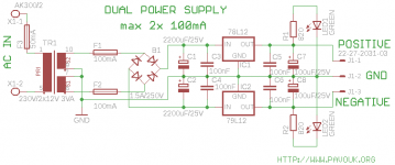
I assembled a simple dual voltage regulator for an op-amp, based on couple 7812;7912 IC's, pretty much one like this:

The thing is i get nice and steady 12V on the positive side and -24V on the negative side.( I tried reassembling in multiple variations and diode/bridge configurations and get same values, so i think i did not mess up the reversed pin configuration on 7912 ) As my tranny is 2x18V(0.052A) I'm assuming the negative IC can't handle the input voltage.. So is there any cheaper way of lowering input voltage for the negative IC rather than buying a lower voltage tranny?
Thanks for any info!
I assembled a simple dual voltage regulator for an op-amp, based on couple 7812;7912 IC's, pretty much one like this:
The thing is i get nice and steady 12V on the positive side and -24V on the negative side.( I tried reassembling in multiple variations and diode/bridge configurations and get same values, so i think i did not mess up the reversed pin configuration on 7912 ) As my tranny is 2x18V(0.052A) I'm assuming the negative IC can't handle the input voltage.. So is there any cheaper way of lowering input voltage for the negative IC rather than buying a lower voltage tranny?
Thanks for any info!
Attachments
Don't forget the 79L has a different pin out to the 78L.
Thanks for the heads up , but i tried to avoid that from the start , as stated in the post.
So you get 36V between positive and negative out ???The thing is i get nice and steady 12V on the positive side and -24V on the negative side.
Mona
So you get 36V between positive and negative out ???
Mona
Correct
Your schematic is a standard regulator and should work like a dream. The tab is connected to pin 2 on both regulators.
i know right, the thing is the IC's are not equally matched and are not of the same make or model.. input voltage might be just a tad too high for the 7912, I wonder how could I test if thats the case.. some load on the negative side before the IC?
so what is the input voltage?
Inputs are both the same for 7812 and for 7912(multimeter shows about 25V) by datasheet it should be working, but I just found some guy has tested it with different inputs and the IC started acting out when the Voltage went higher than 20V.. I think i need to try one more chip at least before replacing the tranny..
I seem to recall that the 79 regulators have a minimum load current that needs to be drawn. Perhaps 10ma or so. The 820 ohm and LED would just about do that but it would be worth tagging another load onto the negative rail and seeing if it fixes the issue.
Also look at adding reverse biased diodes across each reg from input to output. There can be issues at power on when odd things happen.
Also look at adding reverse biased diodes across each reg from input to output. There can be issues at power on when odd things happen.
the regulator shuts down, if its getting too hot. If it is passing the input voltage through, like in your circuit, it is most probably miswired. Just check your circuit again!Inputs are both the same for 7812 and for 7912(multimeter shows about 25V) by datasheet it should be working, but I just found some guy has tested it with different inputs and the IC started acting out when the Voltage went higher than 20V.. I think i need to try one more chip at least before replacing the tranny..
")
I seem to recall that the 79 regulators have a minimum load current that needs to be drawn. Perhaps 10ma or so. The 820 ohm and LED would just about do that but it would be worth tagging another load onto the negative rail and seeing if it fixes the issue.
Also look at adding reverse biased diodes across each reg from input to output. There can be issues at power on when odd things happen.
I added the diodes already, and will now try to load a LED, thanks!
Just one other quick point.
A 1000uF cap on a regulator output isn't good practice. You should be looking at values of around 10uF. The regulator does the regulating
I added the load with LED and Voila! now I get a stable -11.8 Thanks for a quick Insight guys ! much appreciated! I have 100uF on the Output, should I swap them for 10uF? thanks again!
Billy it seems the schematic you posted did not reflect what you built. When asking for help it is important to say exactly what you are doing, else people assume that what you showed is what you did.
Sorry my bad, the only thing that is different from my circuit are the bloody LED's...
I'm such a dumbass, didnt think they are there not just for aestetics...
Sorry my bad, the only thing that is different from my circuit are the bloody LED's...
...and the caps and the diodes.
- Status
- This old topic is closed. If you want to reopen this topic, contact a moderator using the "Report Post" button.
- Home
- Amplifiers
- Power Supplies
- Simple Voltage Regulator Circuit issue