I need to make a power supply that will run +/-15v @ 10-40amps. I want super regulator level performance.
In LTspice I tried adapting the Jung super regulator for this purpose using the output transistors in darlington config but after a few amps it just stops working properly @15v no matter what I do to it.
What should I do to achieve what I need?
In LTspice I tried adapting the Jung super regulator for this purpose using the output transistors in darlington config but after a few amps it just stops working properly @15v no matter what I do to it.
What should I do to achieve what I need?
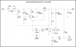
The "Jung Super Regulator", is it the one appended here?
If it is this one, it has an LM317 at the input that can only handle 1.5Amp. The design is a double, cascaded regulator system.
First, you need to get the LM317 out if you want 10-40Amps.
If it is this one, it has an LM317 at the input that can only handle 1.5Amp. The design is a double, cascaded regulator system.
First, you need to get the LM317 out if you want 10-40Amps.
Attachments
This is the one I was trying to alter
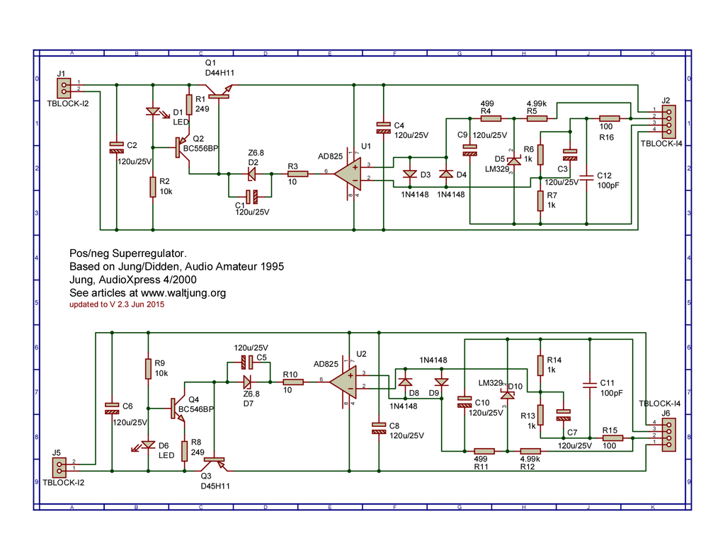
No LM317. The problem is after a few amps the regulator stops regulating and the voltage does not settle where it should.
This does not happen if I set Vout high enough, but trying to get 15v or less out of it @ high amps does not work in spice.
No LM317. The problem is after a few amps the regulator stops regulating and the voltage does not settle where it should.
This does not happen if I set Vout high enough, but trying to get 15v or less out of it @ high amps does not work in spice.
Darlington config reduces the requirement to negligible levels.40 amps current delivery would require either many parallel series pass transistors and a drive circuit to match
I was using the D45h11What power transistor model are you using in LTSpice?
I need to make a power supply that will run +/-15v @ 10-40amps. I want super regulator level performance.
In LTspice I tried adapting the Jung super regulator for this purpose using the output transistors in darlington config but after a few amps it just stops working properly @15v no matter what I do to it.
What should I do to achieve what I need?
Post the .asc file.
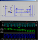
Ouch. Notwithstanding numerous other mistakes you have implemented an oscillator. I have tidied up your circuit.
D45H11 is only good to 10A continuous and its beta crashes at high currents. No idea why you are supplying the circuit with 145V... other stuff.
D45H11 is only good to 10A continuous and its beta crashes at high currents. No idea why you are supplying the circuit with 145V... other stuff.
Attachments
Yeah I'm aware the DH4511 is not suitable for 40A, I would simply parallel them. I was feeding it with 145v because for unknown reasons the circuit would occasionally work if I fed it high voltages.
Can you explain to me what makes the circuit an oscillator? It works fine at lower currents.
Can you explain to me what makes the circuit an oscillator? It works fine at lower currents.
Last edited:
Since you've only simulated so far, and (in the nicest possible way) clearly don't understand how to achieve what you want in plain 'buildability' terms - I suggest you have a read of this article as an insight:
High Current 13.8V Power Supply
- I'm not suggesting you use 2N3055s at all, but it should give you a clear insight into what it takes in hardware and other considerations to deliver even a simple and reliable 13.8-15v / 600w linear regulated supply. Set aside your 'super-reg performance' notion for now - you can't get there from here - just yet.
And yes - what's the target application that demands such high current anyway? Don't confuse 'output current capacity' with 'low output impedance' (the latter is easy, and may be all you need.)
Last edited:
The purpose is for a class A direct drive ribbon amp I'm building with a potential maximum idle of 40A and current swings of half the idle.
I know you are going to tell me not to go with such an inefficient design but perish the thought")
In reality I expect to use it at about 10A idle, not 40A. But I don't have the details of the speaker fully worked out yet so I could end up going much higher than 10A.
Because the current swings are so high I need good regulation. I'm unwilling to compromise on performance for this build so I want super reg levels of performance.
I read the article you linked but I didn't really learn anything from it. I built a 100v 2A version of the super reg that works fine.
I still don't understand why the super reg spice file does not work properly at high currents.
I know you are going to tell me not to go with such an inefficient design but perish the thought
In reality I expect to use it at about 10A idle, not 40A. But I don't have the details of the speaker fully worked out yet so I could end up going much higher than 10A.
Because the current swings are so high I need good regulation. I'm unwilling to compromise on performance for this build so I want super reg levels of performance.
I read the article you linked but I didn't really learn anything from it. I built a 100v 2A version of the super reg that works fine.
I still don't understand why the super reg spice file does not work properly at high currents.
Last edited:
Given you expect to have to operate devices in parallel then why not do so in Spice...? Once you have done that then you still have to look at the nominal behaviour of the devices you are going to use. In particular current gain vs Vce and other parameters.
As Mooly and others suggest you will still probably be on a Highway to Fail... even if you do resort to Mosfets.
Have you considered transformer coupling?
...
As Mooly and others suggest you will still probably be on a Highway to Fail... even if you do resort to Mosfets.
Have you considered transformer coupling?
...
Attachments
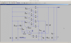
Of course I did parallel them in spice but not quite in the manner you have done. I didn't use the added resistors. I'm guessing the emitter resistors are to facilitate current sharing but what are other resistors between the darlington for?Given you expect to have to operate devices in parallel then why not do so in Spice...?
But whyAs Mooly and others suggest you will still probably be on a Highway to Fail... even if you do resort to Mosfets.
I don't see the insurmountable obstacle you allude to.I refuseHave you considered transformer coupling?
My failure to add R5-6-7-8-9 in your schematic was the cause of my woes. Adding them to mine solved the issue. What are they for?
I'm surprised they had any effect. They do not appear to in my model. Otherwise they are termed Base Stopper Resistors. Single and/or multiple devices are known to cause problems when driven from low impedance sources especially with capacitative loads.
Knowing why, something to do with junction capacitances and negative impedances, is well above my pay grade so I just stick them in as a matter of course. They also act as fuses, use metal film ones, should one of your power devices decide to kick the bucket it save the driver stage.
Either way you are going to end up with a shed load of dissipation using bi-polars, not that you care. Mosfets will be a better bet and you might wish to look into feeding them with a synchronous buck regulator controlling the headroom.
Still don't see the problem with transformers. After all valve amps use them.
A mosfet is not a current amplifier so that would no longer make it a jung regulator since the opamp will not be working as a mini shunt reg.Either way you are going to end up with a shed load of dissipation using bi-polars, not that you care. Mosfets will be a better bet and you might wish to look into feeding them with a synchronous buck regulator controlling the headroom.
This leads me to a possibly stupid question. What is the advantage of the jung regulator vs a normal opamp feedback regulator with a mosfet that you are suggesting I use?
Transformers are reactive and have a laundry list of issues, good ones are extremely expensive to make and even then they will never be perfect.Still don't see the problem with transformers. After all valve amps use them.
The AD825 is not a transconductance amplifier. That is, it has a low output impedance. This means the bipolar is being used in transconductance mode much like a MOSFET.A mosfet is not a current amplifier so that would no longer make it a jung regulator since the opamp will not be working as a mini shunt reg.
This leads me to a possibly stupid question. What is the advantage of the jung regulator vs a normal opamp feedback regulator with a mosfet that you are suggesting I use?
I would also consider an IGBT (like a FET-BJT darlington). This could allow for better power efficiency, depending on how you arrange it, and they are intended for very high current applications. The more powerful and the more devices you use the slower the thing gets so Jung's AD825 with a GBP of some 20MHz will not be suitable. You will almost certainly have to slow the feedback loop down to keep the thing properly stable.
Be aware that this is no novice design challenge. You can't just slap a load of transistors in parallel and expect it to work properly or for any length of time. Do not trust LTSpice to accurately reflect reality; it gets you in the right ballpark but that's all you should count on. You can do this right, just don't skimp on doing your homework.
Last edited:
I never meant that it was a transconductance amplifier. I meant that a bipolar transistor is a current amplifier. The AD825 is shunting the current that is not needed to drive the base of the transistor, thus putting in into class A operation. This is the claimed advantage of the jung version but, why does that really matter?The AD825 is not a transconductance amplifier. That is, it has a low output impedance. This means the bipolar is being used in transconductance mode much like a MOSFET.
I have to admit I'm terrible at high speed circuit stuff and stability issues. What sort of homework are we talking about? What are the issues I need to watch out for? What parameters will spice be "off" on?Do not trust LTSpice to accurately reflect reality; it gets you in the right ballpark but that's all you should count on. You can do this right, just don't skimp on doing your homework.
Last edited:
- Status
- This old topic is closed. If you want to reopen this topic, contact a moderator using the "Report Post" button.
- Home
- Amplifiers
- Power Supplies
- High current high performance power supply?