MorbidFractal: Are you saying that D5 solves the PIV problem for rectifiers?
trobbins: Are you saying that I don't have to worry about the PIV issue because the sims are wrong about it being a problem?
Sorry if these are dumb questions, but I am a choke input virgin.
As Trobbins suggests I am probably over-thinking things as a result of the Simulation blowing up. The additional diode may help with the simulation but otherwise be superfluous.
I also have experience of simulations generating Giga-Volts that needed a little bit of nursing but I cannot strictly claim that the problem did not really exist.
I'll give a little bit of detail later but in respect of PIV being exceeded I would suggest you only really need to be bothered if the excess PIV is derived from a true voltage source or a source with significant energy.
The following suggestion might be slightly dangerous but you can happily send semiconductors, I would assume valves as well but they will be more robust, into breakdown and, as long as the event does not cumulatively result in excessive dissipation, they will recover and carry on working.
YMMV so probably best to adhere to the absolute maximums in the data-sheets unless specific data is given.
I have previously mentioned a push-pull converter and that is something I looked into some time ago using simulation. As I say that was some time ago and I've just recalled as a result of your, not so, dumb questions.
Similar to your circuit the transformer has two centre tapped secondaries with two rectifier diodes connected to the filter inductor.
During primary switch dead, or off, time the inductor current is meant to free-wheel through the diodes connected in parallel through the transformer secondaries. It does but...
If, in the simulation, you give the transformer windings some value for or idea of leakage inductance you end up with Giga-Volts in the simulation.
You have to think a bit about how currents in various items transfer during the switching cycle but it is a 'real' thing both in simulation and in real life.
Probably more so in real life for a hard switched SMPS in as much as snubbing is usually require in order to deal with the resulting ringing in the waveforms... You might not see it in voltage terms but it can play havoc with the current waveforms
Overall it may be more benign in your circuit but it is 'a thing'. It may not be as destructive as the simulation suggests but a couple of cents for a 1N4007 gives some peace of mind.
I'll try to re-create my old thoughts and publish some examples.
Thanks again for the replies. It seems the easiest solution to the PIV problem is to use a 5R4 as suggested earlier. I’m going to order a bunch, as they allow me to use the transformers I have, and they drop the voltage to a useable level. The Potato Mashers are cheap and sort of ugly, albeit in an endearing way. I’ll post a sim of the power supply for your consideration based on that.
I read an article by Thorsten Loesch about his Legacy 300B that was very interesting with respect to his recommendations in regard to PSU total resistance and capacitance. His recommended PSU for that project is based on 5AR4s and 6AS7s, and I have all the parts for it except the ZZ1000, which is inexpensive. It’s a complete departure from a choke input filter, however. This is the link for the article....
http://community.fortunecity.ws/rivendell/xentar/1179/projects/legacy/Legacy.html
Any comments on it?
Putting 420Vdc across the regulator pot is unnecessarily risky.
Strange comment on power supply raw side being 'brawny but fast', yet heater raw supply is the opposite with 10,000uF, and no effort to suppress rectification related noise.
I'd be careful not to do a hot turn-on, as the 300B will likely go full on.
The parallel SV83 cathode bypass caps are a worry.
The connection configuration for the dual GZ34 rectifier is I think much riskier than putting the plates in each device in parallel. Those valves will go gassy at some stage, and having plate-plate voltage within the same tube seems riskier to me. There is also no over-current protection.
I’m likely to stick to the choke input filter, as it is simpler. I just thought the Loesch power supply was an interesting option, and one I was completely unfamiliar with. What is the concern with the parallel cathode bypass caps on the SV83? Do you prefer a single quality capacitor instead? His ideas about having as small a resistance as possible in the power supply seems to make sense intuitively. Connecting the rectifiers in parallel instead is easy enough. I’ve never connected rectifiers as he does in his schematic, does it result in the same output voltages as a parallel connection? Also, what would be a better option than the pot that concerns you?
A modern radial electrolytic meant for switchmode use will easily have low esr out beyond 1Meg. Paralleling different caps can easily result in impedance peaks from resonances - a few good threads on this forum about that.What is the concern with the parallel cathode bypass caps on the SV83? Do you prefer a single quality capacitor instead?
YesI’ve never connected rectifiers as he does in his schematic, does it result in the same output voltages as a parallel connection?
Insert top and bottom padding resistors to soak up most of the 420V, so that the pot only experiences say 50-100V or whatever voltage span is needed for setting regulated output voltage. A failsafe connection of the wiper to the top arm of the pot would also be appropriate - pot wiper contacts don't always stay healthy over the years, depending on the pot type.Also, what would be a better option than the pot that concerns you?
I bought a half dozen of the Coleman regulators, and will use a pair of them for the 300B heaters. I’ll probably use AC on the SV83/EL84 heaters. I like the idea of a two stage circuit, and of using SV83/EL84, as I have many NOS pairs. I use 6P15P-ER in a Decware SE84CS clone, and love it as an output tube. I’m hoping it will serve well as a pre-amp tube for the 300B.
trobbins: Given the fixes you suggest are done, what do you think of Loesch’s main circuit? I started off thinking I was going to build one of the many 6SN7/6SL7 plus 300B circuits that can be found online, or the Bugle, but the idea of a single stage with a SV83 is very tempting....
I'm not really in to directly heated cathode output stages, or that form of hi-fi, so my comments were more from practical design view. It's an amp and should do the job - as indicated, the 300B and output transformer are the big hitters - as long as all other circuit aspects are ok then they won't enter in to the performance imho.
Putting 420Vdc across the regulator pot is unnecessarily risky....
There used to be pots rated for that. Big, expensive.
I think the US "Military 2W" pot is OK for 500V. I have run one at 330V fearlessly and with fine result.
The fact the pot goes all the way both ways is IMHO pointless, even reckless. This allows a swing from 80V (except the EF86 may bottom first) to "infinity" ("800V" at 10% rotation, when there's only 540V to work with). The right answer is a 5.38:1 division, +/-10% for VR tube deviation and possible op-point choice.
However I'm not inclined to work out 5.38 in Ohms because I think a 1938 triode will be perfectly happy with a 1938 power supply: simple. C-L-C filtering.
Last edited:
Thanks for the input trobbins and PRR. My inclination is to go with a traditional power supply as per PRRs recommendation. I'll do an LCLCL with a 5R4. It's much less complicated, and something I'm accustomed to building. Also, I have the parts for it. According to Thorsten, when such a power supply is implemented instead of the one in his schematic, there are a couple of modifications he suggests.
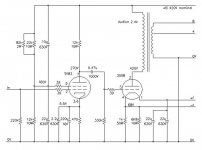
Specifically he said,
"The Amp schematic I provided MUST be used with the powersupply published with it. If you do not do that change the circuit by adding 1K/100uF filtering to the Anode supply of theEL84 and take the capacitor between screengrid and +B away.
Also change the output stage (if you use self biasing) to use a 47/50uF cathode bypass capacitor and a 12uF MKP Capacitor between cathode & +B.
That will do quite nicely using standard LC filtered supplies...
As for the 300B, I like it best at 350V/60mA and with a 5K load instead of 2K5,good for around 6W".
This is what I have simmed so far.....
Attachments
- Status
- This old topic is closed. If you want to reopen this topic, contact a moderator using the "Report Post" button.
- Home
- Amplifiers
- Power Supplies
- choke input power supply question