Yes, I've just tried 1k resistor disconnected from everything, thus measuring just Johnson noise.
Noisy scope, it seems. You can try with various resistor values to learn more about the behaviour of the scope. However as it it seems you can't reliably measure noise.
Try to measure AC component with hand multimeter. Put 1uF in series to + supply than 22k to GND (any value 10-47k will do). Use multimeter to measure AC voltage across the resistor. Same procedure for - rail.
Isn't it almost the same as putting scope in AC coupling mode?
EDITED: Ah, you mean to measure it with multimeter.
check if the setting of the probe is set to 10k (normaly a smal switch on the probe) and the setting on the scope at the correct channel with 10x too.
This one I've checked. 10x is set correctly both on the probe and on the scope.
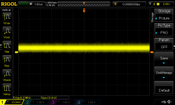
What does the scope show when the probe is directly shorted to ground (clip the ground pin on the probe).
Here's image of what it shows when shorted. Peak to peak voltage is fluctuating from 10mV to 15mV
Attachments
What's the bandwidth of the scope? >88 MHz? ")
I the past two places I've lived, I was able to pick up about 20 mVpp of FM radio on a 400 MHz scope with a scope probe shorted to itself. The signal is picked up by the ground lead usually.
You can try a couple of things: Twirl the ground lead around the scope probe as tightly as you can. Connect the ground clip to the probe tip. This minimizes the loop area, thus the inductive pickup of RF. If this lowers the noise level, you're dealing with inductive pickup. Do your best to minimize the loop area when you take your measurements.
Engage the bandwidth limiter on your scope. If your scope has a bandwidth of 100 MHz or higher, you'll probably have a button you can push to limit the scope bandwidth (thereby the noise bandwidth) to something more reasonable - like 20 MHz.
If none of those work, use a shorting BNC plug (or 50 Ω BNC terminator) to short the input on the scope. If this causes the noise to drop, you have an issue with the probe. If shorting the scope input does not lower the noise, the front-end of the scope is noisy.
Tom
Tried measuring in on and off state. Not much changes in on and off state and during capacitors discharge. Here are images of these two measurements. First is in on state and second is in off state.
If the plots look practically the same with supply on and off (with capacitors empty), then I wouldn't worry about it. Apparently it's some interference picked up by the supply wiring.
Off topic:
@tomchr: Could you put the numbers you put below your posts in this thread: http://www.diyaudio.com/forums/solid-state/318012-low-3.html#post5327608 ? The thread starter tries to collect numbers with lots of zeros.
@tomchr: Could you put the numbers you put below your posts in this thread: http://www.diyaudio.com/forums/solid-state/318012-low-3.html#post5327608 ? The thread starter tries to collect numbers with lots of zeros.
Done. Thanks for the poke.
Now back on topic: I think it would have value to figure out if the probe is bad or if the scope is just noisy. If the scope is noisy, it would be nice to know about it so those of us who care about noise performance get to know which scopes to avoid.
Tom
Now back on topic: I think it would have value to figure out if the probe is bad or if the scope is just noisy. If the scope is noisy, it would be nice to know about it so those of us who care about noise performance get to know which scopes to avoid.
Tom
I don't think this is correct. Thermal noise (Johnson noise) is:If your measurement apparatus were noise-free, we'd expect to see about 80 microvolts of thermal noise from a 1K resistor.
VR = √ ( 4k * T * R * f ) Where ...
k = Boltzmann constant (1.38 x 10⁻²³)
T = Absolute temperature (Kelvin)
R = Resistance in ohms
f = Noise bandwidth in Hertz
For 22°C room temperature, 20,000 Hertz bandwidth, and 1000Ω resistance. that's ~571 nVolts of noise, or 0.571 uVolts.
Assuming a wide bandwidth scope, 1 kohm and 100 pF scope and 1:1 probe capacitance, the noise bandwidth would be 1/(4RC) = 2.5 MHz (as opposed to the half power bandwidth, which would be 1/(2 pi RC)). The RMS thermal noise at 22 degrees Celsius is then about 6.3836 uV (which, by the way, depends only on temperature and capacitance and equals sqrt(kT/C)). The quasi-peak-to-peak noise is about 6 times higher, so roughly 38 uV.
In any case, it seems likely to me that the thread starter is looking at interference picked up by the wiring of his power supply.
In any case, it seems likely to me that the thread starter is looking at interference picked up by the wiring of his power supply.
Last edited:
Marcel, I own a scope just like the one whose screen capture image is attached to post #1. Its probes (Rigol P/N RP3300) are 10X, and according to the datasheet, the probe bandwidth is DC to 350 MHz. Input resistance is 10 megohms ±2% and input capacitance is 16pF ±5pF.
Original poster "belyakove" confirmed in post #25 that both the probe and the scope vertical amplifier menu, were set to 10X.
Since 16mV was observed across a 1K resistor, and 16 mV is much greater than the theoretical prediction, we conclude that the displayed noise is greater than the actual noise. Perhaps due to excessive area in the probetip-to-ground current loop. Setting the Bandwidth Limit switch to 20 MHz would help somewhat.
Last edited:
Here are the schematics. As mentioned on it, 100nF output caps were replaced with 10uF tantalum.
It is PSU producing +/- 12V and +5V for micro controller. but for now I'm measuring only 12V part
The LM317 regulator you show, with 10uF tantalum, will be unstable. Substitute instead 100uF aluminum electrolytic.
This infomercial via youtube is about 50% promo, and 50% learning -- but what you'll see is that a very low ESR cap causes a sharp peak in the phase margin (Q) of the regulator.
YouTube
Picotest makes nice gear, but the setup they show will set you back a kilobuck!
Worth reading -- Jim Williams excerpted some material from TEK on proper use of probes -- starts at page 69: http://cds.linear.com/docs/en/application-note/an47fa.pdf
With a passive 1:10 probe you have 9 Mohm in parallel with 10 pF to 20 pF in between the 1 kohm resistor and the scope input, so it is not surprising that you don't see the noise of the 1 kohm resistor.
Nonetheless, if there were no other noise sources than the 9 Mohm of the probe, the 1 Mohm of the scope and the 1 kohm, you still should see a noise of sqrt(kT/C) RMS or 6 sqrt(kT/C) quasi-peak-peak at the scope input, but you would interpret it as a 10 times bigger signal at the input of the probe. Neglecting the capacitor in the probe and assuming cable plus scope input capacitance to be 100 pF, that explains about 380 uV quasi-peak-peak. The rest of the 16 mV must be noise of the scope or interference that's picked up somehow.
Nonetheless, if there were no other noise sources than the 9 Mohm of the probe, the 1 Mohm of the scope and the 1 kohm, you still should see a noise of sqrt(kT/C) RMS or 6 sqrt(kT/C) quasi-peak-peak at the scope input, but you would interpret it as a 10 times bigger signal at the input of the probe. Neglecting the capacitor in the probe and assuming cable plus scope input capacitance to be 100 pF, that explains about 380 uV quasi-peak-peak. The rest of the 16 mV must be noise of the scope or interference that's picked up somehow.
Yes, you have a valid point. I was thinking in terms of audio. So, substituting 20 MHz for bandwidth (a common setting used on Tektronix oscilloscopes) would result in 18.1uVolts rms (50.88 uV p-p) of noise from a 1KΩ resistor.A bandwidth of only 20 kHz would be very small for an oscilloscope, and oscilloscopes display quasi-peak-to-peak rather than RMS values (when you look at the traces, that is).
- Status
- This old topic is closed. If you want to reopen this topic, contact a moderator using the "Report Post" button.
- Home
- Amplifiers
- Power Supplies
- LM317/337 ripple/noise/oscillation