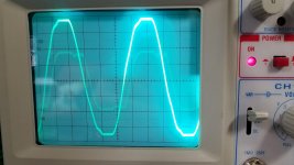
Definitely just got a smoking gun. Here's a couple dual trace shots of the HT and Aux supply. The brighter is the HV winding, the LV is faint. I've never seen anything like this before...it appears the energy from the HV winding is propping up the Aux winding voltage, not allowing it to change. What is this even?
Attachments
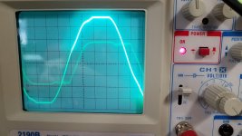
Given that your scope probe gnd is at the neg end of the bridge for each trace, and you have shifted the trace down to allow the full B+ range on the screen, then the flat top and bottom sections are when the bridge diodes are conducting and the winding end is clamped either one diode drop away from gnd or B+.
When the bridge diodes are not clamping the winding ends, then there are only stray capacitances charging up and down to control the voltages that you are probing.
Lets follow the LV winding trace first - it appears to start getting clamped before the HV, and un-clamps about the same time as the HV, and the edges appear a little rounder (which is likely just the channel gain not overlaying the waveforms, but could also be related to the diode voltage drop as a % of the waveform p-p voltage).
I'm thinking the LV trace then doesn't change much for a while because of the large variation in schottky diode capacitance with voltage. The diode that was just conducting exhibits a lot of capacitance when the junction has close to 0V across it, whereas the other diode in that side of the bridge arm is significantly reverse biased and exhibits a much lower capacitance. The winding current that is charging/discharging those diode junction capacitances is not large as it is related to dV/dt, and dV/dt is relatively low for the LV winding as compared to the HV winding. Hence it takes a while for the voltage on that winding end to be charged up enough so that the previously conducting diode capacitance falls enough to not constrain the winding end voltage (and both winding ends get 'clamped' by their previously conducting diode capacitances in the same manner).
In post #11, pic 1, that region of fuzz/noise is during the time when just diode capacitances are determining your trace voltage waveform. That fuzz could be related to diode turn-off energy in one/all the windings trying to find winding current paths to take - but also could be related to you probe gnd position. The advantage of the tuned snubber on each secondary winding is that it can rapidly attenuate the winding currents that appear to be causing that fuzz.
But this is probably just an aside to your main hassle - but none the less worth appreciating.
Last edited:
Thank you for your reply!
valve rectifier is not possible.
)
Did you use Schottky diodes ? You can get bad switching noise with normal diodes.
I made that mistake in a valve mixer, the hum was terrible.
I looked on power supply and there were big switching spikes from the diodes.
Try using HER158G's.
The whole reason I went with a toroid was because they were supposed to NOT spew out as much EMI as EI types, and many design choices that I made were to reduce and avoid this in the first place.
IMO that is a misunderstanding.
In toroidal transformers coupling from primary to secondary(ies) is better than in EI transformers; ideally we wish coupling only of the 50/60 Hz line frequency, but toroids maintain coupling up to much higher frequencies and that's not what we want.
I did not hear you mention that there are screens between primary and secondaries; these help to shunt unwanted stray capacitance.
But this is probably just an aside to your main hassle - but none the less worth appreciating.
First thank you for the excellent explanation, sincerely. But I really was hoping you wouldn't say that.
")
After a little more experimentation, I found that if either LV supply fuse was removed, the waveform looked fine. It's only when both are active. Would it be a bad idea to swap the XFMR leads on the Aux supply since the 2 LV supplies are relatively the same? I'm thinking we could maybe cancel some noise that way since the currents will be out of phase.
Just to verify the toroid is culprit can u unscrew the cnt bolt and rotate and vary its angle. Have the guitar laying so the noise is obvious. If it is the toroid the noise will change if not it is not the toroid. I think...
I tried this and no, it doesn't seem to matter. Which is making me wonder because it surely has to be magnetic in nature since the guitar is pickup source.
Did you use Schottky diodes ? You can get bad switching noise with normal diodes.
I made that mistake in a valve mixer, the hum was terrible.
I looked on power supply and there were big switching spikes from the diodes.
Try using HER158G's.
Sweet, a valve mixer!? That's awesome.
Ya, all Schottkys. Cree SiC C3D0206F on the HV (which look very comparable to the HERs) and STPS2150s on the LV supply.
IMO that is a misunderstanding.
In toroidal transformers coupling from primary to secondary(ies) is better than in EI transformers; ideally we wish coupling only of the 50/60 Hz line frequency, but toroids maintain coupling up to much higher frequencies and that's not what we want.
I did not hear you mention that there are screens between primary and secondaries; these help to shunt unwanted stray capacitance.
No, I chose to not go with a screen and I'm regretting that now I think, lol. I think I thought my line filter/GOSS band would be enough. This could also explain the noise level discrepancy between this build and the professional one with the EI core. I just repeated the spectrum analyzer test and found that mine is actually 1dB lower in noise over the entire spectrum, but like 10 db higher in the 500 Hz to 5kHz range (which is what I hear).
Is there any harm in grounding the Goss band to (hopefully) give some of that noise an easier path back to it's source than the guitar? I read somewhere (Rod Elliot's site I think) that this does help a bit rather than leaving it floating.
A belly band would normally be connected to the core, and the core would normally be connected to chassis - as a safety measure for an EI core transformer. Not connecting the belly band to chassis, if you have that ability, would be my concern, although I can appreciate that the band would be likely double insulated so there would be no safety benefit.
How are you doing the spectrum measurement?
Each of the winding supplies is using a regulator. Each of the uses of the regulated voltages is unlikely to notice some ripple AC on them.
DC heaters at best are likely to lower the noise floor by about 10-20dB compared to standard AC heaters when both methods are properly implemented, so suppressing the AC on the DC heater supply by more than what a regulator can simply do, has imho no benefit.
Similarly for a push-pull output stage B+ supply, and a control supply.
How are you doing the spectrum measurement?
The peak of the charging current pulse increases with filter capacitance, but plateau's, as indicated by the Schade curves (eg. in linked article post #8). It would be worth your effort to appreciate where you may sit on the Schade design curves for each winding supply (although that would require measuring winding resistance which may not be easy). You can then contemplate what the affect may be to reduce first filter capacitance.So, I started thinking about the current pulse, and my first thought was to simply remove a cap from each supply, cutting the reservoir in half. But I realized that would increase the charge pulse's current because the load stays the same (but the pulse width would be wider). The only way to reduce the charge pulses and to increase their width is to add resistance to the XFMR/BR/Reservoir loop. This problem seems to be a case of the dark side of trying to be too perfect: toroid transformer, schottky diodes, high value, low ESR caps in parallel (which halves the ESR). I likely designed this problem in!
Each of the winding supplies is using a regulator. Each of the uses of the regulated voltages is unlikely to notice some ripple AC on them.
DC heaters at best are likely to lower the noise floor by about 10-20dB compared to standard AC heaters when both methods are properly implemented, so suppressing the AC on the DC heater supply by more than what a regulator can simply do, has imho no benefit.
Similarly for a push-pull output stage B+ supply, and a control supply.
Last edited:
A belly band would normally be connected to the core, and the core would normally be connected to chassis - as a safety measure for an EI core transformer. Not connecting the belly band to chassis, if you have that ability, would be my concern, although I can appreciate that the band would be likely double insulated so there would be no safety benefit.
How are you doing the spectrum measurement?
Ah I see. On mine the band is outside of the insulating tape and merely slips over the transformer (so I can remove it) and is covered in tape but no wire. I never understood how it worked as a "magnetic shield" floating, and the manufacturer sort of dodged the question as if they didn't know either, lol. In my experience so far, grounding metal that is floating always makes a noise improvement (like the pole pieces on guitar pickups, potentiometer bodies, etc.).
For the spectrum measurement, I downloaded a standalone program from here: Audio Spectrum Analyser - free software
Then I just set the guitar on a stand, ran the preamp into a speaker simulator into my A/D converter. Likely not a perfect solution for true A/B comparison but even with it running in real time you can clearly see that my build has far more hash in the 500Hz to 5kHz range. I can run the test again and screenshot for fun.
The peak of the charging current pulse increases with filter capacitance, but plateau's, as indicated by the Schade curves (eg. in linked article post #8). It would be worth your effort to appreciate where you may sit on the Schade design curves for each winding supply (although that would require measuring winding resistance which may not be easy). You can then contemplate what the affect may be to reduce first filter capacitance.
Ah, I've saved that article and read it twice but of course missed the significance of that graph. That will be my study tomorrow. In reality, it wouldn't be that hard to do what you said in your first post (small reservoir, then RC into a large cap)...I'd just have to cut and peel some foil. I'm sure I've got some lower value 25V caps laying around to play with.
Each of the winding supplies is using a regulator. Each of the uses of the regulated voltages is unlikely to notice some ripple AC on them.
DC heaters at best are likely to lower the noise floor by about 10-20dB compared to standard AC heaters when both methods are properly implemented, so suppressing the AC on the DC heater supply by more than what a regulator can simply do, has imho no benefit.
Similarly for a push-pull output stage B+ supply, and a control supply.
Ya, I agree 100% which is why I considered that the 2nd caps may not be necessary. But further study and simulation showed like considerably more current, with the same pulse width if I recall so I was deterred.
I did over build this for sure and I'm extremely happy with it's performance in all the other areas save the buzz. There's a silkiness to the sound that the professional unit can't come close to which is pretty validating!
Thank you soo much for all your help!
One more comment is that the secondary winding current pulses have a harmonic spectrum.
At one limit scenario, where there is no output filter capacitance (ie. resistive load), and so the winding has simplistically only mains fundamental frequency current flow with no higher harmonics. In reality, the mains AC waveform is not a clean sine wave, and is often seen as flat topped (due perhaps to equipment that use inordinately large amounts of first filter capacitance :-( ), so the secondary waveform will have higher frequency harmonics.
As first filter capacitance value increases, the winding current pulse increases in peak level and reduces in width from 180 deg. The mains frequency odd harmonic levels start to grow in magnitude.
In post#1, the chassis is referred to as 'thick steel'. Does that mean all sides and top-bottom are thick steel, and in place when you do your guitar testing?
Last edited:
I tried this and no, it doesn't seem to matter. Which is making me wonder because it surely has to be magnetic in nature since the guitar is pickup source.
So its not the toroid! No need to spend time on that... It must be the rectifiers or something in the supply circuit. Are u using full wave rectification on all windings? If half wave u may build dc bias on the core since its not a symmetrical load. How many secondary windings? Is there a winding being used to supply several rectifier/circuits?
Interwinding screen is added capacitance, it does not "shunt unwanted stray capacitance"...............
I did not hear you mention that there are screens between primary and secondaries; these help to shunt unwanted stray capacitance.
When you couple that capacitance to the enclosure, the LC becomes a high pass filter that takes interference to the enclosure.
The Gauss band is isolated from the windings and from the enclosure. Do not try adding a conductive link to the Gauss band.........Is there any harm in grounding the Goss band to (hopefully) give some of that noise an easier path back to it's source than the guitar? I read somewhere (Rod Elliot's site I think) that this does help a bit rather than leaving it floating.
I lean to agree. Those little C0Gs may be pulling hard and fast on the rectifier giving very fast rise time to the current pulses. V (radiated)=L*di/dt so try keep di small and dt large.c92 c118 c125 put 10ohms in series
c97 c121 c126 remove...
c137 10 ohms in series
10 ohms in series with F1
0,2 ohms in series with F2 and F3
And dc blocker on the primary
Now it will be dead quiet!!
Sorry I've been MIA, there was a lot to try and I was being meticulous about recording results and experimenting.
So is there a sort of optimum design guideline? In other words, the to find the first cap value, the cap should be sized for XX% ripple voltage, then the "real" reservoir should be XX times C1?
The entire chassis is .0598" (16 gauge) steel, and the faceplate is .105" (12 gauge). For testing I have the top and faceplate off, so just the front backing, bottom and rear are in place. I was doing it this way so I could rotate the transformer and use the guitar as a sniffer.
One more comment is that the secondary winding current pulses have a harmonic spectrum.
At one limit scenario, where there is no output filter capacitance (ie. resistive load), and so the winding has simplistically only mains fundamental frequency current flow with no higher harmonics. In reality, the mains AC waveform is not a clean sine wave, and is often seen as flat topped (due perhaps to equipment that use inordinately large amounts of first filter capacitance :-( ), so the secondary waveform will have higher frequency harmonics.
As first filter capacitance value increases, the winding current pulse increases in peak level and reduces in width from 180 deg. The mains frequency odd harmonic levels start to grow in magnitude.
So is there a sort of optimum design guideline? In other words, the to find the first cap value, the cap should be sized for XX% ripple voltage, then the "real" reservoir should be XX times C1?
In post#1, the chassis is referred to as 'thick steel'. Does that mean all sides and top-bottom are thick steel, and in place when you do your guitar testing?
The entire chassis is .0598" (16 gauge) steel, and the faceplate is .105" (12 gauge). For testing I have the top and faceplate off, so just the front backing, bottom and rear are in place. I was doing it this way so I could rotate the transformer and use the guitar as a sniffer.
- Status
- This old topic is closed. If you want to reopen this topic, contact a moderator using the "Report Post" button.
- Home
- Amplifiers
- Power Supplies
- Toroid transformer noise