Good morning
I refurbished a Harman Kardon HS500 as defect. i changes all caps on the SMPs and others on the amp side.
Since yesterday the amp is ready and is "burn in" - about 16 hours. (yes i have a seperate room to do this )
)
now in the morning a realised a strange noise comming from the SMPs board.
its a klick klack from a relais and on one of the coils are doing strange "noise"!!!
klickl klack..fiep fiep..klick klack fiep fipe...continiously...
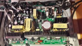
on the pic from the open device all of the diodes on both collings are cold. i do not mentioned that this board is working. i check the sound and the power..it seams that every hting is still working for louder volumes too.
i send the service manual too
thanks for your support diy
I refurbished a Harman Kardon HS500 as defect. i changes all caps on the SMPs and others on the amp side.
Since yesterday the amp is ready and is "burn in" - about 16 hours. (yes i have a seperate room to do this
)now in the morning a realised a strange noise comming from the SMPs board.
its a klick klack from a relais and on one of the coils are doing strange "noise"!!!
klickl klack..fiep fiep..klick klack fiep fipe...continiously...
on the pic from the open device all of the diodes on both collings are cold. i do not mentioned that this board is working. i check the sound and the power..it seams that every hting is still working for louder volumes too.
i send the service manual too
thanks for your support diy
Attachments
Last edited:
..i know that no relais is inside but it sounds like this.
actually i try to searching for more detailed information.
if i turn the amp on ist starting slower than the final frequenz (every second = 1 HZ klick klack with piep). if i switch to stand by this sound getting stopped.
did i change the from caps??? i choose low esr with 10000h duarability. rubicons panasonic....
Rubycon 1189-1884-ND
Rubycon 1189-1869-ND
Rubycon 1189-1869-ND
Nichicon 493-1622-ND
Panasonic P122383-ND
Panasonic P122382-ND
United Chemicon 565-4459-ND
Rubycon 1189-2239-ND
Panasonic P13478-ND
Rubycon 1189-1878-ND
just to remind you.the sound is still fine and the sound is not getting distroyed if i push more power from the amp.
i am getting crazy......its a uncomfortable feeling that something is doing strange but its working...
ideas???
Burble.. Do you have an oscilloscope?
Transformers/Inductors going clack are sometimes indicative of some form of protection circuitry kicking in and out or otherwise cycling things. You can also get it when you overvoltage electrolytics.
Looking at the, horrible, circuit diagram it would seem that supply to the ML4800 comes via Q502, PMOS, from the 'housekeeping' supply generated by U503. That's driven by Opto U505 based on something else.
Poke around in that general area to check signals are solid. Take care though. You are on the primary side so ideally you should be using an isolating transformer to power things.
Burble.. Do you have an oscilloscope?
Transformers/Inductors going clack are sometimes indicative of some form of protection circuitry kicking in and out or otherwise cycling things. You can also get it when you overvoltage electrolytics.
Looking at the, horrible, circuit diagram it would seem that supply to the ML4800 comes via Q502, PMOS, from the 'housekeeping' supply generated by U503. That's driven by Opto U505 based on something else.
Poke around in that general area to check signals are solid. Take care though. You are on the primary side so ideally you should be using an isolating transformer to power things.
Thanks. But i have no isolated Transformers, no Chance to Power my osciloscope with batteries. Just DMM.
Thanks a lot.
Hi
actually the amp is switched and connected of since we wrote this tread.
so thanks...
no isolated probe...i will try it on the weekend thanks a lot !
sorry i want to write is switched off and disconnected....
test are on the weekend...
Hello
i did some measurements with DMM under 8ohms/50Watt load resistor each channels -stereo with radio as input source - parallel on one channel i connect a loudspeaker to listen to the radio.
tthe pcb is in the device and i cant find the Z503 and the R598 or R597 on to top side?
directly on the Z503 i measure 1,74 - 1,82 Volts - according to the schematic its a zener diode with 15Volts??
from GND to the Kadode i measure -186,6 Volts
i checked all connectors:
CN 508 is a 4 pin connector with GND and USB5V ....5,20V its ok
CN505 is a 5pin connector with (measurments ar in brackets)
GND ,5V(4,98V), -12(-12,17), GND, 12(12,07)....its ok
CN503 is a 6 pin connector
GND,S-T(4,92V), V5(5,22)GND, comes from CN508 pin 5,6 (5,30 each),...its ok
CN504 is a 13pin connector
pin GND,S5(4,98), GND,A5(4,97), D5(4,97),GND,3,3(3,28),GND,-12(-12,17), 12(12,07), GND,V5((5,23), V12 (0..zero..should be 12V because its comming from U510-KA7812 + EC512 and L508 are not existing on this board....i do not change something...just the caps ....i swear)...?
its ok....
CN506 is a 4 pin connector
2 pin 34V (34,70) and 2 pins GND (watch out the colors are black+white for 34V and black +white for GND ???!!!!
its ok...
the sound is actuall not click clack it is the noisy piep from a smps.
so whats next i can check?
thanks for helping
i did some measurements with DMM under 8ohms/50Watt load resistor each channels -stereo with radio as input source - parallel on one channel i connect a loudspeaker to listen to the radio.
tthe pcb is in the device and i cant find the Z503 and the R598 or R597 on to top side?
directly on the Z503 i measure 1,74 - 1,82 Volts - according to the schematic its a zener diode with 15Volts??
from GND to the Kadode i measure -186,6 Volts
i checked all connectors:
CN 508 is a 4 pin connector with GND and USB5V ....5,20V its ok
CN505 is a 5pin connector with (measurments ar in brackets)
GND ,5V(4,98V), -12(-12,17), GND, 12(12,07)....its ok
CN503 is a 6 pin connector
GND,S-T(4,92V), V5(5,22)GND, comes from CN508 pin 5,6 (5,30 each),...its ok
CN504 is a 13pin connector
pin GND,S5(4,98), GND,A5(4,97), D5(4,97),GND,3,3(3,28),GND,-12(-12,17), 12(12,07), GND,V5((5,23), V12 (0..zero..should be 12V because its comming from U510-KA7812 + EC512 and L508 are not existing on this board....i do not change something...just the caps ....i swear
)...?its ok....
CN506 is a 4 pin connector
2 pin 34V (34,70) and 2 pins GND (watch out the colors are black+white for 34V and black +white for GND ???!!!!
its ok...
the sound is actuall not click clack it is the noisy piep from a smps.
so whats next i can check?
thanks for helping
Last edited:
...small power test is actually starting
i push over this 50Watt/8 ohm resistors load each stereo channel...just to realise if this click clack is starting with more power over the amp.
its nearly on the volume max!!
with no speakers connected i can hear from the amp pcb the radio ??!!...normal???
i push over this 50Watt/8 ohm resistors load each stereo channel...just to realise if this click clack is starting with more power over the amp.
its nearly on the volume max!!
with no speakers connected i can hear from the amp pcb the radio ??!!...normal???
Last edited:
The sound is actuall not click clack it is the noisy piep from a smps. So whats next i can check?
Thanks for helping
Ahhh. You mean a high pitched squeal from the power supply?
Looking at how the ML4800 is being used on your circuit diagram it is implementing Voltage Mode Control with feedback just after L502 through the KA431 and the opto-isolator next to it, U502. L503 is additional post feedback filtering.
R591/592/593, 6 x 0R1 [16mR] seem to implement an output current limit with U506 of about 3A. It might also provide some damping for L503/EC507.
Anyway. With Voltage Mode Feedback you have to take into account that L502/EC505/EC506 form a second order section.
Without looking harder I may have missed something but it seems that the circuit relies on ESR in EC505/EC506 to introduce a zero and cross over the loop first order.
You say you have replaced these/all capacitors. It may have been the case that EC505/EC506 were not low ESR devices and you have replaced them with low ESR devices....
Do you still have the originals and can you check their manufacturer/part number?
If not then I would suggest that you find replacements characterised as being General Purpose with an ESR of about 500mR. That of itself might be a bit hard if you cannot decipher the data sheets.
A possible quick check would be to see if things improve or change to any degree if you remove one of them. Short term that will not damage things.
thanks morbid..its my first SMPS
the EC505/506 are replaced by nichocon UHE series 493-1622-ND 100µF 50V.
the olds are the green CapXON 1000µF 50V...GF 105°C ........partly some caps were blown on the top...
looks similar to me...
actually the noise is gone...after 30 min on 8 ohms and 30 min on 4ohm resistor load each channel no click clack..??...strange for me
actually the amp is playing on my KEF Q100 without starnge noise since 1hour or more......no click clack is comming from the smps.
everything is fine...strange...
thanks a lot
50 1000
Attachments
From my days of working with SMPS. For a quick look around the transformers and chokes without worrying about isolation, just wind a small coil with hookup wire and feed this into your scope. It might help.
hi Gholl
Do you mean i should take a inductor like a probe and measure with scope some leakage at the transformers?
chris
...Looks like I was/am wrong. I assume your 100uF was a mistype and you meant 1000uf.
Looking through the data sheets you have provided the ESR of the devices is similar enough such that it should not be a problem. A bit more thought required.
The suggestion by Gholl is cute. Not an inductor. Form a coil around a pencil... 5 to 10 turns enamelled copper wire... take it off and hook it up to your probe.
...Looks like I was/am wrong. I assume your 100uF was a mistype and you meant 1000uf.
Looking through the data sheets you have provided the ESR of the devices is similar enough such that it should not be a problem. A bit more thought required.
The suggestion by Gholl is cute. Not an inductor. Form a coil around a pencil... 5 to 10 turns enamelled copper wire... take it off and hook it up to your probe.
hi
oh..yes its a typo...it is 1000µF 50V cap..you are right.
i have some coils from an old denon AVR1804..this is an air coil with about 5 windings or so.
actually the topic looks like closed for me now.
no strange noise is comming by the smps during load tests and sound check with loud volume.but i will do this probe and check around the tranformers...but not today.
i did this last year...
Pimp my DAC - new caps
thanks
- Status
- This old topic is closed. If you want to reopen this topic, contact a moderator using the "Report Post" button.
- Home
- Amplifiers
- Power Supplies
- ...klick klack at SMPS ??...urgent!