In the above power amp example, the zener is used to set the current, not the other way round using a current source to support a zener, Eg like using a current source instead of R4. I wouldn't doubt 1/hoe is easily ~ 1M for a lightly biased signal transistor. I picked 50K as the worst case of an ole cheap power transistor, the value is a merely a 'stake in the ground'. I reckon any good college text for microelectronics using a Hyprid Pi model will show how to derive it from the 'family of curves' or the early voltage. Basically hoe is not a controlled parameter, and for power supply stuff it's almost always ignored E.g "It's somewhere way up there" not so much for a common emitter gain stage it often sets the max gain. iN any case the goal of using a current source in most any circuit is to approach an ideal current source , a stable value w/ high impedance.
Emitter degeneration is used to lessen the dependence on both Vbe and hfe variations in a circuit (AC + DC feedback), it has zero effect on 1/hoe for a given Ib.
Emitter degeneration is used to lessen the dependence on both Vbe and hfe variations in a circuit (AC + DC feedback), it has zero effect on 1/hoe for a given Ib.
Last edited:
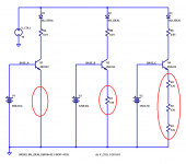
Here are three current source circuits with three different values of emitter degeneration resistance: 0 ohms, 120 ohms, and 360 ohms; please see the red ovals in Figure 1 below.
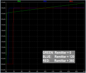
When we sweep the collector voltage and measure the collector current, we see that each of the three circuits behaves more or less like a 5.0 milliamp current source: Figure 2 below. Current is 5 mA, more or less independent of voltage.
(Ideal diodes D1-D3 prevent unwanted "reverse current" from flowing when the collector voltage is less than the base voltage)
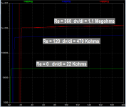
I asked LTSPICE to measure the output slope (the "output impedance") of the three current sources in Figure 2. LTSPICE's calculated values are displayed in Figure 3. {numerical differentiation goes bananas at low voltages (Vce < Vbe) where Iout is zero}
Figure 3 shows that adding emitter degeneration to a current source circuit, can increase its output impedance dramatically.
_
When we sweep the collector voltage and measure the collector current, we see that each of the three circuits behaves more or less like a 5.0 milliamp current source: Figure 2 below. Current is 5 mA, more or less independent of voltage.
(Ideal diodes D1-D3 prevent unwanted "reverse current" from flowing when the collector voltage is less than the base voltage)
I asked LTSPICE to measure the output slope (the "output impedance") of the three current sources in Figure 2. LTSPICE's calculated values are displayed in Figure 3. {numerical differentiation goes bananas at low voltages (Vce < Vbe) where Iout is zero}
Figure 3 shows that adding emitter degeneration to a current source circuit, can increase its output impedance dramatically.
_
Attachments
Thanks, interesting you chose a fixed battery to generate the base current. I don't know about your models but I would never use a transistor circuit like the 1st one.
By definition hoe stays the same. You've just added another term using Re tied onto the Hybrid Pi model. Best to find a good circuit for the application and then generate a model for it. My point being that in most cases any value of the active current source resistance (1/hoe or modified ) is gonna be a factor of 10 or more than the simple resistors case, in setting the zener current. Perhaps some emitter resistance is inherent for good stable design.
By definition hoe stays the same. You've just added another term using Re tied onto the Hybrid Pi model. Best to find a good circuit for the application and then generate a model for it. My point being that in most cases any value of the active current source resistance (1/hoe or modified ) is gonna be a factor of 10 or more than the simple resistors case, in setting the zener current. Perhaps some emitter resistance is inherent for good stable design.
Last edited:
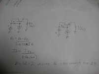
It's a fun little piece of circuit analysis to derive the final result:
Grind through the math yourself, you'll find it rewarding.
If you want to look it up in a textbook, I bet you'll find a lot more has been published using the hybrid-pi transistor model (whose CE output impedance is named "ro" rather than "(1/hoe)"). If your first instinct is to reach for a copy of Gray and Meyer's all-encompassing textbook: it uses hybrid-pi exclusively.
The output impedance "Zout" of a common emitter stage with emitter degeneration resistor Remitter, smoothly and continuously varies from Zout=(1/hoe) when Remitter=0, to Zout=((1+Beta)/hoe) when Remitter increases towards infinity.
The important rule of thumb is: adding emitter degeneration to a 1-transistor common emitter current source, will give you at most a factor of 1+Beta improvement in output impedance. If you need even higher output impedance, you gotta switch to a different circuit (having more than 1 transistor).Grind through the math yourself, you'll find it rewarding.
If you want to look it up in a textbook, I bet you'll find a lot more has been published using the hybrid-pi transistor model (whose CE output impedance is named "ro" rather than "(1/hoe)"). If your first instinct is to reach for a copy of Gray and Meyer's all-encompassing textbook: it uses hybrid-pi exclusively.
I have always worked out one of these approximations , an estimate of RL would be the opamp max draw and the sum of stuff such as signal shaping branches in this case.
I suppose this allows iZ to be reduced, and decreases current induced noise. For that goal, maybe an igfet would be a better choice than bjt, then add a filter + feedback cap to farther reduce noise. The filter cap would be at the R1/ZD1 junction. Those have not really helped much, but maybe something better than NPO's may have lower ESR and actually make a significant improvement. Then with the igfet, the filter cap could be more effective since there is no discharge through the base.
It may be interesting to see how well it regulates with the igfet. Probably needs a minimum RL and current limit on the supply side. Might end up as a fairly good low grade high current supply. A giant shrimp thing.
Attachments
Last edited:
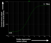
The output impedance "Zout" of a common emitter stage with emitter degeneration resistor Remitter grows smoothly and continuously, when Remitter increases from zero to infinity
It's a fun little problem, to devise a way to make LTSPICE measure and plot this. You'll get results as shown below. I used the same simulated device type (LTSPICE 2N2222) as in post #22 above.
Zout smoothly and continuously increases from 22 Kohms to 4.7 Megohms, as the emitter degeneration resistor varies from zero to infinity. The ratio of these two numbers is indeed (1+Beta) {at Vce=10, Ice=5mA}, just as pencil and paper analysis predicts.
_
Attachments
What chances are there that the cheap, easy, Zener, resistor, and capacitor used to make secondary voltages, say for a pre-amp or equalizer, being noisy as they are, would add overhead to the opamp's ability to reject noises and other undesired effects on it's ability to operate in micro-distortion performance. (what a sentence !)
Depends on the complexity of the preamp/equalizer.
If zeners are what u have and u dont wanna buy something else, try it. The cap will shunt the zener noise. Go mad with an additional RC filter.
A zener is the simplest shunt regulator, and HiFi nuts love shunt regs. Less is more. win-win!
I'd check temp drift. Zeners > 5ish volts drift positive, <5ish volts negative. Common practice is one 6.2V zeners in series with silicon diodes for near zero tempco. You probably know this. Two strings of that is only ca 14V, but perhaps close enough?
Next check for output impedance. Does it supply what is needed? Local bypassing on each opamp probably gives u all u need so it is likely just fine.
Can u afford to add an emitter follower? Suddenly your circuit aint so simple...
I'd do it and not tell...uggh
I didn't know about the tempco compensation trick, thanks, I'll try it.
The power supply isn't the real intent of the thread but I was curious if all the bad stuff the opamp is supposed to be self compensating for , were thrown at it at once, would it not be able to keep up with mayhem. But could deal with one major problem at a time.
The power supply isn't the real intent of the thread but I was curious if all the bad stuff the opamp is supposed to be self compensating for , were thrown at it at once, would it not be able to keep up with mayhem. But could deal with one major problem at a time.
- Status
- This old topic is closed. If you want to reopen this topic, contact a moderator using the "Report Post" button.
- Home
- Amplifiers
- Power Supplies
- Simple Zener Secondary Voltage Regulators