Project is a 24v Bravo v2. No crazy mods yet, just the IRL510 + better lm317 swap
Trying to decide how I want to power this thing. I was thinking dual LM1084(Paralleled) and have been playing around in LTSpice with a design, but honestly not sure if I want to commit.
Question 1
How many amps does this thing pull, cranked without the modified lm317 circuits and with the changed adj resistance(increased voltage) of the lm317?
Question 2
Can I feed this with a +12/-12 type supply design using a regulator with the equivalent negative counterpart? Or am I asking for issues with tube heaters and other components?
Question 2a
Wouldn't it see "GND"(-12) as reference anyways? lol I think that is how that works.
Question 3
Toroidal transformer voltage! 120v(60Hz)
Let's say I go with a traditional +24/0 supply, what am I looking at for the transformer specs?
My calculations(probably wrong) are leading me to think about going for 20v(In parallel)load toroidal at about 35Va.
Question 4
Am I correct here:
20VAC x 1.414 = 28.3
28.3-(1.07x2) = 26.14VDC
This looks to be hitting the target vin-vout max of 1.5v of the LM1084's with a little room. Cutting it too close?
Diodes = BYV27-200
Toroid = ??? can't find a 20v toroidal transformer
An 18v seems to low, a 24v transformer is just too much any way I calculate it.
I do have a 24v toroidal, but the thing is a whopping 7amps.....
The conundrum.
Transformer voltage choice")
Any insight would be greatly appreciated!
Trying to decide how I want to power this thing. I was thinking dual LM1084(Paralleled) and have been playing around in LTSpice with a design, but honestly not sure if I want to commit.
Question 1
How many amps does this thing pull, cranked without the modified lm317 circuits and with the changed adj resistance(increased voltage) of the lm317?
Question 2
Can I feed this with a +12/-12 type supply design using a regulator with the equivalent negative counterpart? Or am I asking for issues with tube heaters and other components?
Question 2a
Wouldn't it see "GND"(-12) as reference anyways? lol I think that is how that works.
Question 3
Toroidal transformer voltage! 120v(60Hz)
Let's say I go with a traditional +24/0 supply, what am I looking at for the transformer specs?
My calculations(probably wrong) are leading me to think about going for 20v(In parallel)load toroidal at about 35Va.
Question 4
Am I correct here:
20VAC x 1.414 = 28.3
28.3-(1.07x2) = 26.14VDC
This looks to be hitting the target vin-vout max of 1.5v of the LM1084's with a little room. Cutting it too close?
Diodes = BYV27-200
Toroid = ??? can't find a 20v toroidal transformer
An 18v seems to low, a 24v transformer is just too much any way I calculate it.
I do have a 24v toroidal, but the thing is a whopping 7amps.....
The conundrum.
Transformer voltage choice
Any insight would be greatly appreciated!
A link to the project would help folks who do not have all possible projects memorized.
Is this the $69 "tube" HP amp?
By inspection: the tube needs 12V 0.3A heat. The actual headphone amp could be several designs, but with those heatsinks shouldn't pull over 0.1A per channel, 0.2A. The plate current of 12AU7 is negligible. 0.3A+0.1A+0.1A= 0.5A; round-up to 0.6A DC. The AC Amps rating should be 1.8X or >1.1A; 1.5A may be a standard size.
It pulls what it pulls. Applying for high voltage burns-out the heater. Designing for high current is pointless. (OK, you want a few-second turn-on surge at 2A- most linear supplies tolerate this gracefully.)
18VAC gives 24V DC. If you can't make clean 12V out of twice that, then something else is wrong. 0.6A suggests >600uFd first filter cap. Since the voltage is high already, and will be regulated, I would not super-size that. 1,000uFd is a convenient value.
18VAC, 1.5A (27VA) AC, 1,000uFd, 10 Ohms 5 Watts, 1,000uFd, gives 18V ripple dips. An LM7812 can regulate that to 12V just fine. There is 3.6 Watts in the regulator so it needs a large heatsink, like 2"x3".
I have no idea why you would use dual +/- supplies. It is clearly intended for generic single 12V power. Tube plates are traditionally single-supply. Tube heaters are just light-bulbs and don't need multiple supplies.
That is the one, yes.A link to the project would help folks who do not have all possible projects memorized.
Is this the $69 "tube" HP amp?
I'm actually running a 12AX7.
The heaters are in stock config at the moment.By inspection: the tube needs 12V 0.3A heat. The actual headphone amp could be several designs, but with those heatsinks shouldn't pull over 0.1A per channel, 0.2A. The plate current of 12AU7 is negligible. 0.3A+0.1A+0.1A= 0.5A; round-up to 0.6A DC. The AC Amps rating should be 1.8X or >1.1A; 1.5A may be a standard size.
I do plan on running them in parallel with this R-78B6.5-1.0L at some point in time.
I agree that it pulls what it pulls, trying to spec for max current draw + headroom so the supply doesn't collapse.It pulls what it pulls. Applying for high voltage burns-out the heater. Designing for high current is pointless. (OK, you want a few-second turn-on surge at 2A- most linear supplies tolerate this gracefully.)
The Bravo v2 literally runs on 24v.18VAC gives 24V DC. If you can't make clean 12V out of twice that, then something else is wrong. 0.6A suggests >600uFd first filter cap. Since the voltage is high already, and will be regulated, I would not super-size that. 1,000uFd is a convenient value.
Linear regulators ALWAYS have supersized caps before them and after the rectification point. like 10k uF +, why say otherwise?
The Bravo v2 runs off 24v?18VAC, 1.5A (27VA) AC, 1,000uFd, 10 Ohms 5 Watts, 1,000uFd, gives 18V ripple dips. An LM7812 can regulate that to 12V just fine. There is 3.6 Watts in the regulator so it needs a large heatsink, like 2"x3".
we can calculate heatsink requirements after I figure out what i'm running for the transformer.
Not dual, just a split plus minus design, this thing doesn't have a "GND" so the negative voltage would be reference gnd anyways providing 24 volts?I have no idea why you would use dual +/- supplies. It is clearly intended for generic single 12V power. Tube plates are traditionally single-supply. Tube heaters are just light-bulbs and don't need multiple supplies.
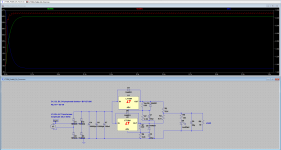
Guess i'll post up my current supply design(not finished) to show what i'm talking about. It is not a split plane design.
Thanks for taking the time to respond, hopefully I cleared some things up.
did you read that other Thread?
Help for PMillett HV regulator
and they linked to
High Voltage Regulator
Help for PMillett HV regulator
and they linked to
High Voltage Regulator
did you read that other Thread?
Help for PMillett HV regulator
and they linked to
High Voltage Regulator
I see a nfet reverse voltage protection(not needed) and R7 used to drop voltage before the lm317.
The problem with "high" voltage (24v) is that these regulators don't like much amp draw, so even if you use say, the discontinued LT1083 which looks like a nice big fat 7 amp draw capable regulator... in reality at such high voltage the amp draw these things are capable og go out the window...usually go under 1 amp. like 820ma.
Two load sharing regulators almost doubles the amperage capability and shares heat.
Those load balance resistors are probably going to be way too expensive to use, so I doubt I want to use this design.
Still floating around some ideas. *shrugs*
Thinking a +/- lm317/337
- Status
- This old topic is closed. If you want to reopen this topic, contact a moderator using the "Report Post" button.
- Home
- Amplifiers
- Power Supplies
- Bravo v2 Power supply design considerations