Hi!
I hope this question hasn't been answered many times before, but at least I haven't found the exact answer I was looking for...
I'm building a stereo amp, based on Thel Accusound Pro modules, where part of the power supply needs to be in a separate enclosure from the enclosure with the actual amplifier.
The power supply enclosure will contain the transformer and part of the capacitors, and the amplifier enclosure the boards and the rest of the caps.
The plan is two use two separate voltages, UB1 (approx 85V DC) and UB2 (approx 90V DC), for the amp modules, using both sets of secondaries from the transformer.
The two enclosures will be connected with Neutrik PowerCon cables, one each for UB and UB 2.
Question is, how do I ground the whole thing for safety and minimal noise?
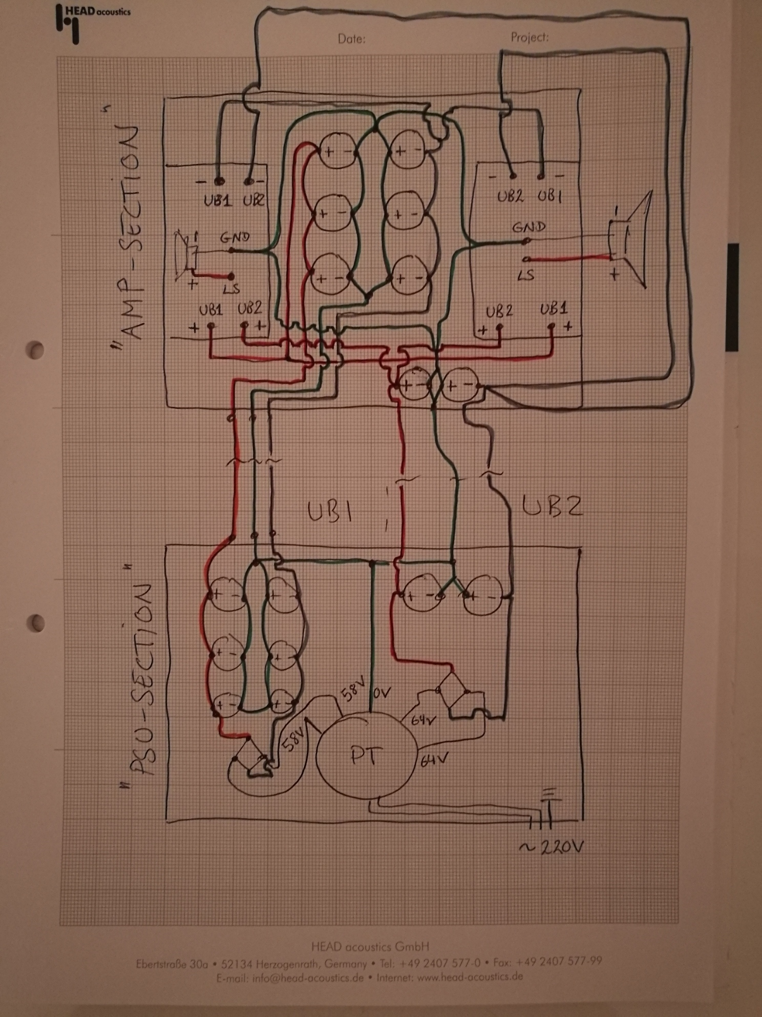
I've drawn up a "diagram", but left out the points where the enclosures are grounded:
Any advice would be very much appreciated!
Cheers
Es
I hope this question hasn't been answered many times before, but at least I haven't found the exact answer I was looking for...
I'm building a stereo amp, based on Thel Accusound Pro modules, where part of the power supply needs to be in a separate enclosure from the enclosure with the actual amplifier.
The power supply enclosure will contain the transformer and part of the capacitors, and the amplifier enclosure the boards and the rest of the caps.
The plan is two use two separate voltages, UB1 (approx 85V DC) and UB2 (approx 90V DC), for the amp modules, using both sets of secondaries from the transformer.
The two enclosures will be connected with Neutrik PowerCon cables, one each for UB and UB 2.
Question is, how do I ground the whole thing for safety and minimal noise?
I've drawn up a "diagram", but left out the points where the enclosures are grounded:
Any advice would be very much appreciated!
Cheers
Es
An externally hosted image should be here but it was not working when we last tested it.
Thanks!For safety, connect the PSU enclosure to mains ground. Connect the amp enclosure to the PSU enclosure.
Choose one point in your audio circuit to connect the audio signal ground to an enclosure.
That is kind of what I was thinking - have a signal ground point in the amp enclosure, connect the PSU to mains ground, and rund a separate ground wire between the two enclosures.
I'll try putting it together like that and report back!
Cheers
Es
Your PSU is wired incorrectly.
You have taken the Centre tap of the secondaries to the OUTPUT of the smoothing bank.
Instead take the Centre Tap to the INPUT of the respective capacitors banks.
Once you have that, you will find that the two capacitor banks share a Zero Volts. That potentially can cause problems in downstream circuits. You must avoid LOOPs in the downstream circuitry that may be affected by interference impinging on that loop.
Thanks guys!
@ Dave Davenport: I've downloaded your doc and had a look at section 4.3, but I'm still not sure I' m on the right track... But many thanks for taking the time to write that up and share it with everyone - drinks are on me next time you're in the Stuttgart area of Germany!
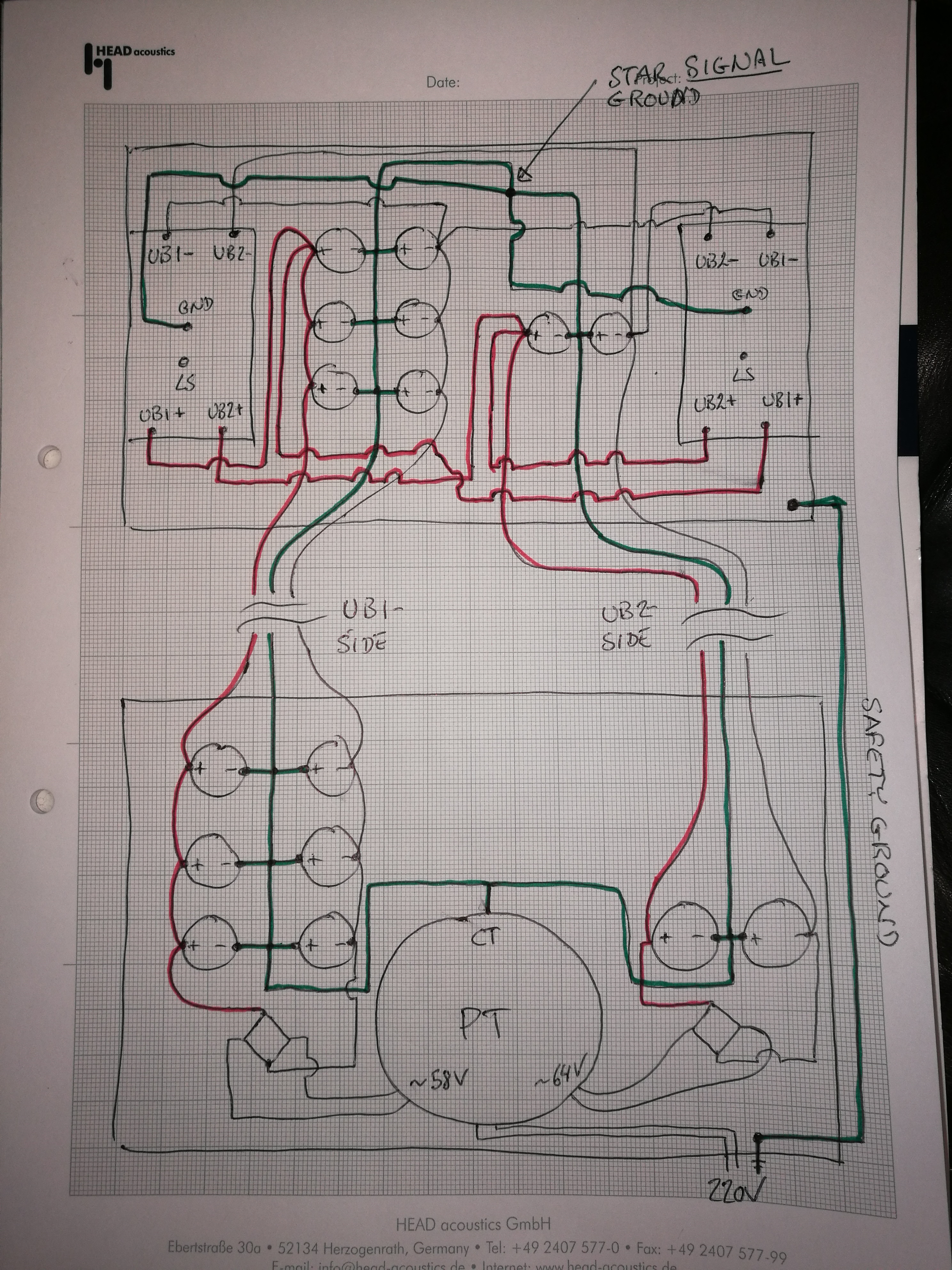
I've now split the centre tap of the PT and fed the inputs of the capacitor banks. UB1+ , UB1 0, UB1- will now go through one cable, UB2+ , UB2 0, UB2- though the other. The safety ground connecting the two enclosures through a separate cable. Will that work?
Cheers
Es
@ Dave Davenport: I've downloaded your doc and had a look at section 4.3, but I'm still not sure I' m on the right track... But many thanks for taking the time to write that up and share it with everyone - drinks are on me next time you're in the Stuttgart area of Germany!
I've now split the centre tap of the PT and fed the inputs of the capacitor banks. UB1+ , UB1 0, UB1- will now go through one cable, UB2+ , UB2 0, UB2- though the other. The safety ground connecting the two enclosures through a separate cable. Will that work?
Cheers
Es
You still have a ground loop, as there are two paths from the CT to the star point. Why do you have two secondaries sharing one CT connection? If the power transformer actually has two separate secondaries each with their own CT then you can build two separate PSUs each with their own centre. Then join the two at the star point.
Your new smoothing cap arrangement is much better.
And you have continued that "in on one side and out from the other side" as the power reaches the amplifiers.
To refine that, look at the transformer through rectifier to the Input of the smoothing caps. This is connected by a 3 wire cable. Twist these three wires to minimise loop area. That minimises interference. At the terminations the termianls and their wires must also maintain that low loop area. Do not build in big loop into current circulation cables.
Look at the output from the smoothing caps that flows to the amplifier. Again you have 3 wires. Use a twisted triplet just like the previous taking care to minimise the Loop Area in the cable and at the terminations.
Sumarising the above.
There should be NO SINGLE cables taking current from Source to Receiver. NEVER.
All current flows around loops. Every microamp that leaves a Source MUST RETURN to that Source. It's that Flow and Return pair of cables that can form LOOPS. It's your job as Builder to identify all those Loops and minimise the LOOP AREAS.
Following on from DF:
If you have one secondary that is centre tapped, then you you can use ONE PSU and that supplies both amplifiers. This will have 3 secondary tappings.
You have two seconadries each with their own centre tap and these are isolated from each other. This will have 6 secondary tappings.
There are two more alterantives:
A Dual secondary has 4 tappings and two tappings are isolated from the other two.
A quadruple secondary that has 8 tappings, each 2 tapping secondary is isolated from all the other secondaries.
Which do you have?
Last edited:
The Protective Earth wire gets connected to the mains Chassis/Enclosure.Is the star ground necessary in the remote amp enclosure? So long as there is a safety earth connection to the power supply enclosure I'd make the "ground" to chassis connection there
That is a SAFETY connection and has absolutely nothing to do with obtaining a good working audio system.
There is a second rule:
All exposed conductive parts should be connected to the Protected Chassis/Enclosure.
Again this has nothing to do with obtaining good quality audio. It is purely SAFETY.
However, both the PE connection and the extra "All exposed parts" connection can give an additional route for interference reaching the audio circuitry.
Scott has mentioned
This is the Safety connection and the only time it ever passes any significant current is when there is a Mains Fault. This means that as Scott has suggested that it does NOT need to be in the amplifier. I tend to agree that the better location is at the PSU Zero Volts. This gives a shorter route for the Mains FAULT Current to escape to the Protective Earth. It's the Low Impedance of this route that allows the Mains Fuse to rupture quickly when there is a catastrophic failure of the Isolation between Mains and Audio.the "ground" to chassis connection there
Hi again,
Were would I be without you guys!?!
The PT I have is this one:
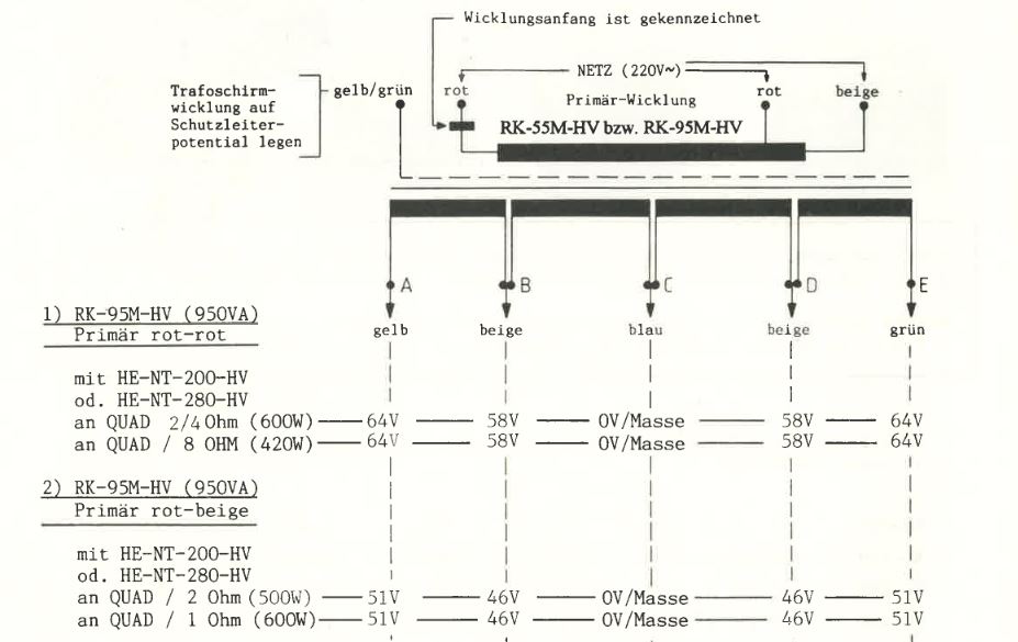
It's only got one centre tap, but two sets of tappings. Will that even work for generating 2 different voltage supplies?
I could also try simplifying matters by just using the 64V tapping for UB1 and completely ignoring the option of the secondary voltage for UB2.
If I do that, I'd have +64V, "0V" and -64V going through a triplet cable between the two enclosures. Can I then run the safety ground as a separate cable between the two enclosures?
Cheers
Es
Were would I be without you guys!?!
The PT I have is this one:
It's only got one centre tap, but two sets of tappings. Will that even work for generating 2 different voltage supplies?
I could also try simplifying matters by just using the 64V tapping for UB1 and completely ignoring the option of the secondary voltage for UB2.
If I do that, I'd have +64V, "0V" and -64V going through a triplet cable between the two enclosures. Can I then run the safety ground as a separate cable between the two enclosures?
Cheers
Es
Probably not, you'd have to check that the output stage could run at the higher voltage. You could safely use the lower tapping for both the VAS and output stage, but this would restrict the maximum output. It may also be that the higher voltage winding cannot supply the necessary current for the output stageI could also try simplifying matters by just using the 64V tapping for UB1 and completely ignoring the option of the secondary voltage for UB2.
Last edited:
OK. One secondary with one CT means one '0V' line in the PSU and one '0V' wire between enclosures. You can still have two bridges and two lots of reservoir caps, but you need to be careful how you arrange them so ground currents (especially charging pulses) do not infect DC.
1. the audio star ground, which is the reference point for signal voltages
2. the connection between the star ground and the chassis, which is for safety purposes.
Perhaps you think, as many seem to, that the star ground must be physically mounted on the chassis and so concepts 1 and 2 become physically one component thus mixing up signal currents and fault currents.
You seem to be conflating two quite different concepts:scottjoplin said:Is the star ground necessary in the remote amp enclosure? So long as there is a safety earth connection to the power supply enclosure I'd make the "ground" to chassis connection there
1. the audio star ground, which is the reference point for signal voltages
2. the connection between the star ground and the chassis, which is for safety purposes.
Perhaps you think, as many seem to, that the star ground must be physically mounted on the chassis and so concepts 1 and 2 become physically one component thus mixing up signal currents and fault currents.
Appearances can be deceptive, I asked a question and then answered it. The star I was referring to was the one he shows in the amp enclosure, there is no need for it to be there.You seem to be conflating two quite different concepts:
1. the audio star ground, which is the reference point for signal voltages
2. the connection between the star ground and the chassis, which is for safety purposes.
Perhaps you think, as many seem to, that the star ground must be physically mounted on the chassis and so concepts 1 and 2 become physically one component thus mixing up signal currents and fault currents.
I'm presuming the amp case is metal, that will provide shielding, what has the Powercon got to do with it?
He said he's using two separate enclosures. And he also said he's connecting the 2 enclosures with powercon. Besides the possible confusion of the amp getting an actual 220v powercon plugged into it, I'd also suggest fuses, in both enclosures.
Edit: Just in case it wasn't clear: A metal case does not protect from getting radio interference over the antenna.. er, power wires into it.
Last edited:
- Status
- This old topic is closed. If you want to reopen this topic, contact a moderator using the "Report Post" button.
- Home
- Amplifiers
- Power Supplies
- Grounding with separate enclosures?