I have said it before and I will say it again...
You really really need to be concerned about loop stability.
I have lost the link but there was some chap on You Tube who spent what must have been years Vlogging about a regulated power supply that never worked because there was no concept about the loop gain/stability of the circuit.
The, lack of, solution was very similar to some of the things that have been posted to this thread and it spent all of its time oscillating.
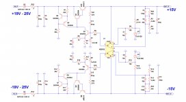
I do not know anything like it all but I almost know this much. For the moment I'll just leave the schematic, not his.. mine, here and, perhaps, talk about it later.
You really really need to be concerned about loop stability.
I have lost the link but there was some chap on You Tube who spent what must have been years Vlogging about a regulated power supply that never worked because there was no concept about the loop gain/stability of the circuit.
The, lack of, solution was very similar to some of the things that have been posted to this thread and it spent all of its time oscillating.
I do not know anything like it all but I almost know this much. For the moment I'll just leave the schematic, not his.. mine, here and, perhaps, talk about it later.
Attachments
Just before I go off and buy some more Cider... One of the keys to this sort of stuff is that the feedback/stability is dependent on the load. In this case that would be C2 and its associated ESR, R9... and, of course, what you dangle on the end of your supply.
I will be bold and suggest that, unless some idiot comes along and starts slapping extra capacitance on the output coz it reduces something, the load is going to be resistive or a current sink and, as such, if you design your supply to be stable, taking into account its component variances, it will be stable.
All the fans of Three Terminal Voltage regulators will have read the data sheets, cough, and know that strange things happen when you ignore advice about input decoupling and, more importantly, output load capacitance... including ESR.
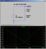
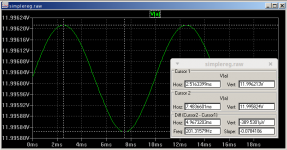
Anyway... Here is our 220uF capacitor with an ESR of 50mR being driven by an 500mA AC Current Source.
It is a DC Pole, XC = 1/2piFC, up to the ESR zero frequency, Fz = 1/2piRC. Phase transitions from -90 degrees, lag, to 0 degrees.
I will be bold and suggest that, unless some idiot comes along and starts slapping extra capacitance on the output coz it reduces something, the load is going to be resistive or a current sink and, as such, if you design your supply to be stable, taking into account its component variances, it will be stable.
All the fans of Three Terminal Voltage regulators will have read the data sheets, cough, and know that strange things happen when you ignore advice about input decoupling and, more importantly, output load capacitance... including ESR.
Anyway... Here is our 220uF capacitor with an ESR of 50mR being driven by an 500mA AC Current Source.
It is a DC Pole, XC = 1/2piFC, up to the ESR zero frequency, Fz = 1/2piRC. Phase transitions from -90 degrees, lag, to 0 degrees.
Attachments
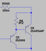
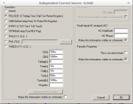
The 500mA current source is from the 'Darlington'. The OP is using a 'Darlington'. Ignoring other stuff I am not confident about supposedly the current gain is Beta1 X Beta 2. Say 250 X 200 or 50,000. Otherwise it varies all over the shop depending on actual current and voltage across the devices plus day of the week.
So we tread on it and put an Emitter resistor in. Small signal 1V on the input base gets converted to 1V across the Emitter resistor and now I get called for my mistake. 500mR gives me 2Amps per Volt driving the output capacitance and its ESR.
So we tread on it and put an Emitter resistor in. Small signal 1V on the input base gets converted to 1V across the Emitter resistor and now I get called for my mistake. 500mR gives me 2Amps per Volt driving the output capacitance and its ESR.
Attachments
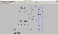
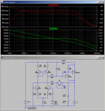
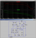
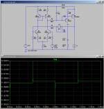
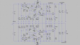
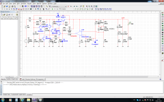
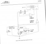
Now we throw in the rest of the circuit. I've gone and relabelled some things. It is almost as simple as you can get.
Q1 and Q2 form a long tailed pair degenerated by R2 and R3. Kittens. We are throwing away gain but if you are just going to pick a couple of the same transistors out of your parts bucket they are unlikely to be matched in terms of offset.
The 'load' is a current mirror, Q3 and Q4. R4 and R5 perform a similar function in respect of unmatched devices. The output, via R6 and C1, throwing away more gain, drives our Darlington.
The loop is broken by AC voltage source, V1. This is the standard trick used to measure 'loop gain'. You plot V(A)/V(B) assuming one of the nodes is low impedance, A. <- That may be wrong but it is near enough.
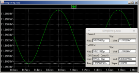
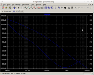
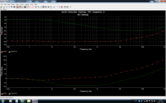
Once upon a time I would also randomly plot AC responses for various nodes in a circuit and gain no idea about the 'loop gain' or overall circuit stability. Run the AC analysis and we get the second picture.
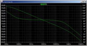
Previously we had the CFILT/Pole RESR/Zero and now we have in effect a Single Pole up to the 0dB loop crossover. For frequencies of interest the circuit is always first order, constant -90 degrees phase shift, and we can claim 'unconditional stability'.
That was thanks to R6 and C1 which act to cancel the RESR/Zero. Loop gain crosses over at about 150KHz, 1A load current, and I guess we might go cry about the 'low' bandwidth. It is even more miserable at 1mA load, third picture...
However the 'thing' is the circuit is still 'unconditionally stable', assuming you do not dangle something nasty on it. Things might be 'improved' but it is really just chasing rainbows.
Q1 and Q2 form a long tailed pair degenerated by R2 and R3. Kittens. We are throwing away gain but if you are just going to pick a couple of the same transistors out of your parts bucket they are unlikely to be matched in terms of offset.
The 'load' is a current mirror, Q3 and Q4. R4 and R5 perform a similar function in respect of unmatched devices. The output, via R6 and C1, throwing away more gain, drives our Darlington.
The loop is broken by AC voltage source, V1. This is the standard trick used to measure 'loop gain'. You plot V(A)/V(B) assuming one of the nodes is low impedance, A. <- That may be wrong but it is near enough.
Once upon a time I would also randomly plot AC responses for various nodes in a circuit and gain no idea about the 'loop gain' or overall circuit stability. Run the AC analysis and we get the second picture.
Previously we had the CFILT/Pole RESR/Zero and now we have in effect a Single Pole up to the 0dB loop crossover. For frequencies of interest the circuit is always first order, constant -90 degrees phase shift, and we can claim 'unconditional stability'.
That was thanks to R6 and C1 which act to cancel the RESR/Zero. Loop gain crosses over at about 150KHz, 1A load current, and I guess we might go cry about the 'low' bandwidth. It is even more miserable at 1mA load, third picture...
However the 'thing' is the circuit is still 'unconditionally stable', assuming you do not dangle something nasty on it. Things might be 'improved' but it is really just chasing rainbows.
Attachments
I suppose I should mention that R11 is there to balance offsets due to input bias currents. Its, standard, value is chosen to, almost, match the parallel value of R9 and R10.
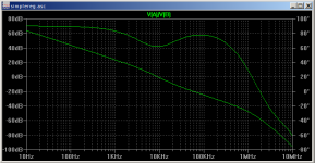
Previous pictures show that the circuit is, nominally, first order up to crossover and then 'something' goes wrong.
Part of my overall ignorance means that I would find it hard to give a complete analysis of the circuit but take a guess that the Darlington is running out of steam. Meaty stuff usually cops out before the small signal stuff.
Plot VB/Ib, input resistance of the Darlington, and... First picture.
The Darlington starts losing the plot at around the same time as the loop gain deviates from being 1st order.
Chasing a small rainbow we can gain a bit, not much, by connecting the collector of Q5 to ground. Second picture.
It is, possibly/probably, indicative of CB capacitance. In this case, unless you are going to exceed the voltage rating of the device it's for free so why not.
Attachments
Last edited:
And... What do you get for your pennies?
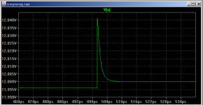
Picture 1) 100mA/1000mA Transient response. Output impedance is about 4mR.
That is a limitation of the DC gain.
Picture 2) Same but close up.
The excursion, 45mV, 900mA X 50mR, is entirely due to the ESR of the output capacitor. The nature of the recovery is down to the circuit being, nominally, entirely first order.
Recovery is about 10uS which is indicative of the loop bandwidth, about 100KHz.
Picture 3) 1000mA Load with 500mA 1KHz Excursion.
Output impedance is 5mR but it will tend to 50mR as the frequency goes up.
Picture 4) 1000mA Load with 100Hz 1V ripple on VCC.
Whatever the dB rejection is in respect of 1V vs 400uV.
Attachments
Super regulator.
No it is not. It is an Oscillator!
Picture 1) Circuit.
Picture 2) Loop Gain.
Picture 3) Transient performance 100mA-1000mA @ 1KHz
Attachments

This is a test of a circuit.
See attached files.
.
Looks like meaningless rubbish to me.
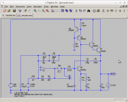
OK.. replace R12 with a pulsed current source. Picture attached.
Run a transient analysis 0 to 100mS.
Publish the results for the output voltage.
Attachments
Looks like meaningless rubbish to me.
OK.. replace R12 with a pulsed current source. Picture attached.
Run a transient analysis 0 to 100mS.
Publish the results for the output voltage.
Silence....?
Poking about elsewhere I come across mention of the Walt Jung "Super Regulator".
http://www.waltjung.org/PDFs/Improved_PN_Regs.pdf
Reading the text the circuit suffers from start-up problems and, more importantly in the present context, stability issues.
I also note that Jenyok appears to link quite regularly to "Drop Shop" versions of implementations for such circuits.
Pffft. I did not even have to read the text.
Word to the wise... If someone tries to sell you a circuit that contains an operational amplifier which is, locally, operated open loop and not intended to function as a comparator then the person concerned, despite their misplaced intentions, is selling you an oscillator.
Thanks.
I think your Figure 8) is quoted in another thread and the originator suggests that the diagram results from a set of LTSpice analysis where the 'models' were 'plugged in' and that was the result of the AC analysis.
The big problem is that LTSpice, and others, will find a DC operating point for the circuit prior to running the analysis and give you a generally meaningless, small signal, answer because there is nothing to 'excite' the model and cause it to fall over.
Fine... stick an AC 1A sink on the output and you might get some concept of output impedance. Stick a 100mA/1000mA 1KHz pulse source on the output and run a transient analysis and watch things fall over...
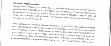
I recommend spending the €0,99 to read the original, rather than relying upon other people's recollection of what they imagine it might or might not contain. Here for example is part of the description of the lab apparatus used to measure the output impedance of all the regulators in the test.
_
_
Attachments
Thanks.
I think your Figure 8) is quoted in another thread and the originator suggests that the diagram results from a set of LTSpice analysis where the 'models' were 'plugged in' and that was the result of the AC analysis.
These are actual measurements. That makes you follow-on sentence meaningless in this context.
Jan
I recommend spending the €0,99 to read the original, rather than relying upon other people's recollection of what they imagine it might or might not contain. Here for example is part of the description of the lab apparatus used to measure the output impedance of all the regulators in the test.
Great. Now I have to set up a new e-mail alias and blah blah blah.
So, as suggested, someone is trying to sell you an oscillator.Postlude: Some thoughts on the Jung/Didden Regulator. Many DIY’ers have tried to improve upon the performance of the Jung/Didden regulator. Quite frankly, this device performs so well that many of the tweaks aren’t just gilding the lily, they impair performance. The AD797 amplifier, owing to its very high bandwidth, can be problematic as it is easily excited into oscillation if strict care is not paid to wiring and shielding. In one case, the AD797 based Jung/Didden regulator was observed oscillating at 2.2MHz when it was removed from its chassis. In another case, the oscillation caused the SSM2019 low noise amplifier to (apparently) rail. On occasion I was able to see several local a.m. radio stations (with energy well above the ambient level at their frequencies) on my HP3577A Spectrum Analyzer when the AD797 regulator was not properly housed. For these listening tests an AD825AR operational amplifier was used without any bypass capacitors or RFI protection.
Attachments

Morbid, what's your beef here? Hundreds of these regulators have been build and work to satisfaction. The issue with the '797 is properly documented, as is good engineering practice. In fact that was already documented in 1994 in the original published series in Audio Amateur.
Do you have any experience with this kind of circuit? I mean practical?
Jan
Do you have any experience with this kind of circuit? I mean practical?
Jan
Morbid, what's your beef here?
I had an issue with JenYok publishing non-functional Spice models.
Hundreds of these regulators have been build and work to satisfaction.
According to Mr Walton many have tried to improve on things and watched them fall over. After all if it is already on the edge what more might you expect.
The issue with the '797 is properly documented, as is good engineering practice. In fact that was already documented in 1994 in the original published series in Audio Amateur.
That sounds like 'good engineering practice'. My design is prone to picking up various AM stations because I do not have a clue about loop compensation but things might be good if you place it in a biscuit tin.
Do you have any experience with this kind of circuit? I mean practical?
Jan
Unfortunately your Straw Man has found me out.
I am not prone to arbitrarily slapping boutique wide bandwidth operational amplifiers into circuits without consideration of the overall design.
As a result I have limited practical experience of this kind of circuit.
Oh...
...This should have important implications to out audio amplifier designs, but, since audio has now entered the state of being a fashion industry, it will not happen. Still, it is nice to at least have the insight.
it always has been as long as you ignore the 'insight'.
Last edited:
As a result I have limited practical experience of this kind of circuit.
OK, fair enough, but then why do you present yourself as the source of The Truth?
Yes many diy'ers make changes to perfectly good circuits, and as a result they have problems. Many here, Jack Walton, Walt Jung, myself, Per-Anders etc. advise and help solving problems for those users.
Why don't you join us with your insight?
Jan
- Status
- This old topic is closed. If you want to reopen this topic, contact a moderator using the "Report Post" button.
- Home
- Amplifiers
- Power Supplies
- Op amp Linear power supply