OK, fair enough, but then why do you present yourself as the source of The Truth?
Jan
I will be wrong but I do not think I did. I just rubbished other people's perception of the truth and gave reasons.
I will be wrong but I do not think I did. I just rubbished other people's perception of the truth and gave reasons.
Reasons? I didn't see you give any 'reasons', though you did rubbish other people's views.
That is so easy to do. For instance, I could conclude from your statement 'a circuit that contains an operational amplifier which is, locally, operated open loop and not intended to function as a comparator' that you don't apparently understand how a feedback regulator works; but what would that accomplish except you getting angry at me?
I would be looking for a more constructive discussion.
Jan
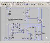
No it is not. It is an Oscillator!
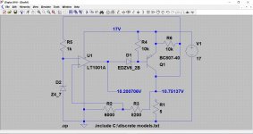
Picture 1) Circuit.
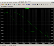
Picture 2) Loop Gain.
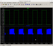
Picture 3) Transient performance 100mA-1000mA @ 1KHz
Why do you replace the D44H11 with a 2N3055 and assume the 330 uF to be perfect?
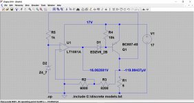
Here is a variant of the Super Regulator that was built and tested with a huge variety of different opamp ICs, opamps which spanned an 80-to-1 ratio of bandwidth. The regulator did not oscillate with any of them. The key to this lack of oscillation may (or may not!) be the use of a very fast, vertical channel MOSFET as the series pass transistor. I've still got a couple blank PCBs if anyone wants to mess around with it further; will gladly send to you for USD $0.85 (to pay for the bubble mailer) plus postage to your address. You can try it with other, pin compatible!, opamps that I did not try.
55 MHz opamp + MOSFET pass xitor in 1 amp Voltage Regulator
_
55 MHz opamp + MOSFET pass xitor in 1 amp Voltage Regulator
_
Last edited:
Why do you replace the D44H11 with a 2N3055 and assume the 330 uF to be perfect?
Closest model in a 'base' LTSpice install. The original circuit used a perfect 330uF capacitor.
Here, now with D44H11
Code:
Version 4
SHEET 1 880 1008
WIRE -704 -304 -736 -304
WIRE -592 -304 -624 -304
WIRE -544 -304 -592 -304
WIRE 32 -304 -464 -304
WIRE 128 -304 32 -304
WIRE 304 -304 128 -304
WIRE 416 -304 304 -304
WIRE 128 -272 128 -304
WIRE -592 -240 -592 -304
WIRE 32 -208 32 -304
WIRE 128 -160 128 -192
WIRE 128 -160 96 -160
WIRE -592 -144 -592 -176
WIRE 128 -80 128 -160
WIRE -592 -32 -592 -64
WIRE 32 -32 32 -112
WIRE 64 -32 32 -32
WIRE 304 16 304 -304
WIRE 32 32 32 -32
WIRE 128 64 128 16
WIRE 240 64 128 64
WIRE 416 96 416 -304
WIRE 32 144 32 112
WIRE 304 144 304 112
WIRE 352 144 304 144
WIRE 304 176 304 144
WIRE -496 288 -608 288
WIRE -448 288 -496 288
WIRE -336 288 -368 288
WIRE -304 288 -336 288
WIRE -192 288 -224 288
WIRE 304 288 304 256
WIRE 304 288 -192 288
WIRE 416 288 416 192
WIRE 416 288 304 288
WIRE -496 384 -496 288
WIRE -448 384 -496 384
WIRE -336 384 -336 288
WIRE -336 384 -384 384
WIRE -304 384 -336 384
WIRE -192 384 -192 288
WIRE -192 384 -240 384
WIRE 192 384 32 384
WIRE 288 384 256 384
WIRE 416 384 416 288
WIRE 416 384 368 384
WIRE 416 416 416 384
WIRE 544 416 416 416
WIRE 656 416 544 416
WIRE 688 416 656 416
WIRE 128 448 128 64
WIRE -496 480 -496 384
WIRE -464 480 -496 480
WIRE -256 496 -400 496
WIRE -224 496 -256 496
WIRE -112 496 -144 496
WIRE -80 496 -112 496
WIRE 32 496 32 384
WIRE 32 496 0 496
WIRE 64 496 32 496
WIRE -464 512 -496 512
WIRE 416 528 416 416
WIRE 544 528 544 416
WIRE -112 576 -112 496
WIRE -48 576 -112 576
WIRE -496 608 -496 512
WIRE -464 608 -496 608
WIRE -352 608 -400 608
WIRE -256 608 -256 496
WIRE -256 608 -288 608
WIRE -48 608 -256 608
WIRE 656 608 656 416
WIRE 128 640 128 544
WIRE 240 640 128 640
WIRE 416 640 416 592
WIRE 544 640 544 592
WIRE -496 656 -496 608
WIRE 240 672 240 640
WIRE -736 768 -736 -304
WIRE -608 768 -608 288
WIRE -496 768 -496 736
WIRE 128 768 128 640
WIRE 240 768 240 736
WIRE 416 768 416 720
WIRE 32 784 32 496
WIRE -736 880 -736 848
WIRE -608 880 -608 848
WIRE -608 880 -736 880
WIRE -496 880 -496 848
WIRE -496 880 -608 880
WIRE 32 880 32 848
WIRE 32 880 -496 880
WIRE 128 880 128 848
WIRE 128 880 32 880
WIRE 240 880 240 848
WIRE 240 880 128 880
WIRE 416 880 416 848
WIRE 416 880 240 880
WIRE 544 880 544 720
WIRE 544 880 416 880
WIRE 656 880 656 688
WIRE 656 880 544 880
WIRE -736 912 -736 880
FLAG -736 912 0
FLAG 32 144 0
FLAG -48 576 A
IOPIN -48 576 Out
FLAG -48 608 B
IOPIN -48 608 Out
FLAG 688 416 VOUT
IOPIN 688 416 Out
FLAG -592 -32 0
SYMBOL npn 240 16 R0
SYMATTR InstName Q1
SYMATTR Value 2N3904
SYMBOL npn 352 96 R0
SYMATTR InstName Q2
SYMATTR Value Qd44h11
SYMBOL pnp 96 -112 R180
WINDOW 0 112 59 Left 2
WINDOW 3 66 31 Left 2
SYMATTR InstName Q3
SYMATTR Value 2N3906
SYMBOL pnp 64 16 M180
WINDOW 0 58 58 Left 2
WINDOW 3 55 33 Left 2
SYMATTR InstName Q4
SYMATTR Value 2N3906
SYMBOL res 112 -288 R0
SYMATTR InstName R3
SYMATTR Value 100R
SYMBOL npn 64 448 R0
SYMATTR InstName Q5
SYMATTR Value 2N3904
SYMBOL res 112 752 R0
WINDOW 0 38 50 Left 2
SYMATTR InstName R6
SYMATTR Value 1K
SYMBOL res 16 480 R90
WINDOW 0 0 56 VBottom 2
WINDOW 3 32 56 VTop 2
SYMATTR InstName R8
SYMATTR Value 511R
SYMBOL Opamps\\opamp -432 560 M180
SYMATTR InstName U1
SYMATTR SpiceLine Aol=1E6
SYMATTR SpiceLine2 GBW=1E7
SYMBOL res 16 16 R0
WINDOW 0 34 46 Left 2
SYMATTR InstName R4
SYMATTR Value 20K
SYMBOL res -624 752 R0
SYMATTR InstName R11
SYMATTR Value 750R
SYMBOL res -352 272 R90
WINDOW 0 0 56 VBottom 2
WINDOW 3 32 56 VTop 2
SYMATTR InstName R10
SYMATTR Value 3K4
SYMBOL res -208 272 R90
WINDOW 0 0 56 VBottom 2
WINDOW 3 32 56 VTop 2
SYMATTR InstName R9
SYMATTR Value 383R
SYMBOL cap -384 368 R90
WINDOW 0 0 32 VBottom 2
WINDOW 3 32 32 VTop 2
SYMATTR InstName C1
SYMATTR Value 22µ
SYMBOL voltage -496 752 R0
WINDOW 0 38 43 Left 2
WINDOW 3 36 72 Left 2
SYMATTR InstName VREF
SYMATTR Value 2.5V
SYMBOL voltage -736 752 R0
WINDOW 0 38 43 Left 2
WINDOW 3 38 70 Left 2
SYMATTR InstName VIN
SYMATTR Value 19V
SYMBOL voltage -128 496 R90
WINDOW 0 -32 56 VBottom 2
WINDOW 3 32 56 VTop 2
WINDOW 123 36 58 VTop 2
WINDOW 39 0 0 Left 2
SYMATTR InstName Vac
SYMATTR Value ""
SYMATTR Value2 AC 1
SYMBOL res -480 752 R180
WINDOW 0 -53 69 Left 2
WINDOW 3 -41 44 Left 2
SYMATTR InstName R12
SYMATTR Value 1K
SYMBOL cap 400 528 R0
WINDOW 0 41 20 Left 2
WINDOW 3 43 45 Left 2
SYMATTR InstName CFB
SYMATTR Value 220µ
SYMBOL res 400 624 R0
WINDOW 0 40 52 Left 2
WINDOW 3 40 75 Left 2
SYMATTR InstName Resrb
SYMATTR Value 10m
SYMBOL cap 224 672 R0
WINDOW 0 45 13 Left 2
WINDOW 3 48 36 Left 2
SYMATTR InstName C4
SYMATTR Value 22µ
SYMBOL res 224 752 R0
WINDOW 0 42 47 Left 2
SYMATTR InstName R7
SYMATTR Value 10R
SYMBOL res 384 368 R90
WINDOW 0 0 56 VBottom 2
WINDOW 3 32 56 VTop 2
SYMATTR InstName R5
SYMATTR Value 270R
SYMBOL cap 256 368 R90
WINDOW 0 0 32 VBottom 2
WINDOW 3 32 32 VTop 2
SYMATTR InstName C3
SYMATTR Value 270p
SYMBOL cap -240 368 R90
WINDOW 0 0 32 VBottom 2
WINDOW 3 32 32 VTop 2
SYMATTR InstName C2
SYMATTR Value 150p
SYMBOL diode -400 592 R90
WINDOW 0 0 32 VBottom 2
WINDOW 3 32 32 VTop 2
SYMATTR InstName D1
SYMATTR Value ZID
SYMBOL diode -352 624 R270
WINDOW 0 32 32 VTop 2
WINDOW 3 0 32 VBottom 2
SYMATTR InstName D2
SYMATTR Value ZID
SYMBOL cap 528 528 R0
WINDOW 0 41 20 Left 2
WINDOW 3 42 48 Left 2
SYMATTR InstName CFC
SYMATTR Value 220µ
SYMBOL res 528 624 R0
WINDOW 0 36 50 Left 2
SYMATTR InstName Resrc
SYMATTR Value 50m
SYMBOL ind 400 752 R0
WINDOW 0 47 42 Left 2
WINDOW 3 47 69 Left 2
SYMATTR InstName L1
SYMATTR Value 5n
SYMBOL diode 48 848 R180
WINDOW 0 91 40 Left 2
WINDOW 3 42 14 Left 2
SYMATTR InstName D3
SYMATTR Value 1N4148
SYMBOL res -608 -320 R90
WINDOW 0 0 56 VBottom 2
WINDOW 3 32 56 VTop 2
SYMATTR InstName R1
SYMATTR Value 1R
SYMBOL res -448 -320 R90
WINDOW 0 0 56 VBottom 2
WINDOW 3 32 56 VTop 2
SYMATTR InstName R2
SYMATTR Value 1R
SYMBOL cap -608 -240 R0
WINDOW 0 44 24 Left 2
WINDOW 3 45 51 Left 2
SYMATTR InstName CFA
SYMATTR Value 470µ
SYMBOL res -608 -160 R0
WINDOW 0 43 45 Left 2
WINDOW 3 45 71 Left 2
SYMATTR InstName Resra
SYMATTR Value 50m
SYMBOL res 640 592 R0
WINDOW 0 44 48 Left 2
WINDOW 3 42 71 Left 2
SYMATTR InstName RLOAD
SYMATTR Value 150R
SYMBOL res 288 160 R0
WINDOW 0 36 52 Left 2
SYMATTR InstName R13
SYMATTR Value 1K
TEXT -608 88 Left 2 !.LIB OPAMP.SUB
TEXT -608 112 Left 2 !.MODEL ZID D(RON=10m ROFF=1E9 VREV=15V)
TEXT -608 136 Left 2 !.ac dec 20 1 1E7
Picture 2) Loop Gain + Phase
Picture 3) 100mA/1000mA 1KHz transient response.
Attachments
Morbid,
look again at your gain/phase plot.
See the change in slope of the gain curve @ 1MHz to 5MHz.
A small change in component values will move that steep part that crosses the 0dB line to a better location and make the circuit stable.
Small changes in device models would be enough to make this circuit stable. Your sim is not proving the circuit is unstable, it is proving you have deliberately massaged the selection of device models to make the circuit perform badly.
I am sure you have the expertise to show what changes are required to make this stable and with adequate phase and gain margins.
Giving that extra information would do your reputation a lot more good than stopping with post 45.
Last edited:
That is so easy to do. For instance, I could conclude from your statement 'a circuit that contains an operational amplifier which is, locally, operated open loop and not intended to function as a comparator' that you don't apparently understand how a feedback regulator works.
Jan
I am sure that you could or would but then I would have to assume that your have not bothered to read my other posts in this thread where I discuss loop gain, how to measure it in Spice and, in part, some of the things you have to do in order to design a robust and stable circuit.
Closest model in a 'base' LTSpice install. The original circuit used a perfect 330uF capacitor.
.
In the documentation as well as here in the thread we have repeatedly made the case to use an output cap with some ESR, NOT a boutique film cap but any lowly electrolytic.
Replacing a D44 with a 3055 and expecting similar results is hilarious. A D44 model can be easily downloaded from the 'net if you take the trouble.
Jan
Last edited:
I am sure that you could or would but then I would have to assume that your have not bothered to read my other posts in this thread where I discuss loop gain, how to measure it in Spice and, in part, some of the things you have to do in order to design a robust and stable circuit.
Your assumption is correct. But the fact remains that your statement 'a circuit that contains an operational amplifier which is, locally, operated open loop and not intended to function as a comparator' could easily be thought to show that you don't apparently understand how a feedback regulator works.
Jan
The regulator did not oscillate with any of them. The key to this lack of oscillation may (or may not!) be the use of a very fast, vertical channel MOSFET as the series pass transistor.
55 MHz opamp + MOSFET pass xitor in 1 amp Voltage Regulator
Your MOSFET behaves as a voltage controlled current source driving the output filter capacitance and its ESR. You get a DC pole with a constant 90 degree phase lag up to the zero frequency, about 50KHz.
Your op-amp has local feedback, C8 47p. Another DC pole. The overall loop will cross over 1st order and will therefore be stable. Within reason it does not matter what bandwidth of opamp you use. It's characteristics are fixed by R13 and C8.
gm for the MOSFET is variable and it also has variable figures for Ciss, Crss and Coss. In your circuit that does not matter so much because the gate resistor which forms a pole with the MOSFET input capacitance is small so that pole will be above the overall cross over frequency of the loop.
Since you already appear to have a model of the circuit try breaking the loop as shown elsewhere in this thread and measure the loop gain. It should be second order, 40dB/Decade, up to the ESR zero and then become first order, 20dB/Decade up to and beyond the crossover frequency.
Small changes in device models would be enough to make this circuit stable. Your sim is not proving the circuit is unstable, it is proving you have deliberately massaged the selection of device models to make the circuit perform badly.
Please... I modelled the original circuit as presented with a 330uF ideal capacitance. Yes the 2N3055 was not as given and not as given when I included the parasitics provided later.
Do try to look at the latest model. It is using a D44H11 and is as close as I can get it to being as later presented so do not accuse me of deliberately massaging things.
Replacing a D44 with a 3055 and expecting similar results is hilarious. A D44 model can be easily downloaded from the 'net if you take the trouble.
Jan
Did you miss the part of Post #45 where I specifically state that I have included a D44 model?
It might be nice to have a 'discussion' but if you are not going to pay attention then there is little to no point.
It is weird that a circuit that apparently works well in real life oscillates in simulations, it is usually the other way around. Is there much difference between different brands of D44H11? There are huge differences in fT and collector-base capacitance between different brands of BD135, could we have something similar here?
A few observations that may or may not help to debug the simulation:
R2 is not in the original circuit. It could increase the impact of the reverse capacitance of the output and driver stages.
The input and output decoupling capacitors have different values than in the original circuit, but not much different. If that's enough to make the circuit oscillate, it is not very robust.
There is one part of the loop that still has a rather ideal model, the NE5532:
SYMBOL Opamps\\opamp -432 560 M180
SYMATTR InstName U1
SYMATTR SpiceLine Aol=1E6
SYMATTR SpiceLine2 GBW=1E7
with antiseries connected Zeners across it to keep the output voltage finite. Do these Zeners have zero capacitance?
A real NE5532 has a kink in its response around 200 kHz due to a pole-zero pair and extra steep roll-off above 10 MHz due to non-dominant poles. I would expect that to only make matters worse, not better, though.
Not quite. Since it's connected as a source follower it behaves as a voltage controlled voltage source with a series resistance of (1/gm).Your MOSFET behaves as a voltage controlled current source driving the output filter capacitance and its ESR.
That is the main result. Stability with all opamps, even the scariest high bandwidth types, is easily achieved.Within reason it does not matter what bandwidth of opamp you use. It's characteristics are fixed by R13 and C8.
Since loop dynamics are set by passive components {remember to include the Thevenin equivalent of R6-RV1-R12} you don't need high precision modeling of the opamp itself. You can simulate using a ridiculously simplified opamp model, even a VCVS with single pole rolloff. Feel free to give it a try.
For stability analysis, the level shift apparatus with its current source support circuitry, can be omitted. So can the careful VREF generation and filtering; leave out all of it and just use a battery.
All, I appreciate all the responses to my original question. Mooly, I tried to reconnect the zener to the output and the circuit still failed to start with the capacitors. The capacitors did help. that circuit regulates to 90 millivolts across the load range of 10 to 50 ohms with the TIP42C. I do not have the equipment to check ripple, like an oscilloscope. I have read all the responses here and some of the circuits I do not have the parts to try the circuit. As I mentioned, I am a basement hobbyist at best learning the basics by trying things I read on the internet and in electronic circuit books. some are successful and others not so much. I do apologize but something are above my education level right now, but I am learning from folks like you. I do know I like the learning process.
Thanks....Mark
Thanks....Mark
Its good to hear you are having fun and enjoying all this ")
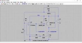
So... not starting up. Hmmm. That's a little unexpected tbh so lets try something really simple such as adding a high value resistor across the series pass transistor which should generate a tiny initial 'difference' voltage between the opamp inputs and so kick start things.
Try something like 10k initially, and if its OK work up in value until the circuit fails to start and then pick something midway... best empirical practice
I suspect a different opamp type would not do this but see how you get on.
Out of interest I can actually get the circuit to fail to start in simulation as in the first picture. Second picture with a resistor R6 added, and here even 100k worked.
Attachments
With the load R1 connected you probably need a lot more to get it to start.
How about this?
-Connect a diode from the collector of Q1 to R5, anode tied to Q1, cathode to R5
-Add a high-valued resistor from V1 to the cathode of the extra diode
A load pulling down the collector of Q1 then can't hamper start-up. After start-up, it is the regulated voltage minus one diode forward drop that supplies the current to the Zener, so the PSRR should not be degraded much.
Thanks Marcel
Curiously, the simulation only failed to start with no load attached. Also, different transistors worked OK which is very odd.
I think you mean like this. Adding just the diode (no resistor) also worked. The peculiarities of LTspice. Remember also the sim is using a tiny transistor to supply 2 amps to the load. Fortunately no hole was burnt into the screen
I like your idea though, it should definitely work under all conditions.
Attachments
That's not so strange: when a circuit has more than one solution, a simulator's DC analysis just more or less randomly converges to one of them. It's not a peculiarity of LTSpice, exceedingly expensive professional simulators have the exact same property.
The circuit you've drawn is precisely what I meant.
The circuit you've drawn is precisely what I meant.
All, I will try this circuit in both configurations, Mooly & Marcelvdg with the resistor added and then the resistor diode. I managed to burn up a 741 and I don't know what I did. It is okay I know I am going to have these "occurrences". I bought 20 741's for $5 they seem to work better than the one i had. I can definitely say adding the capacitors on the output helped the regulation. There is only a 90 MV change between loads and hat is very tolerable to drive tube filaments. I do have two nte928 op amps. Also I have some TL061 & TL071's Jfets and I do not know how to make them work right now. They require dual rail supply (i think) and I do not have anything to power them right now. I am having fun experimenting. I am also going to work on a high B+ voltage regulator for the PAS, but i have to work on that another time. I only need about 10 MA total at 355 VDC and another one regulated at 210 VDC for the Dynamo PAS3. I am in no hurry. Again thanks.
- Status
- This old topic is closed. If you want to reopen this topic, contact a moderator using the "Report Post" button.
- Home
- Amplifiers
- Power Supplies
- Op amp Linear power supply