What is a "single wire pilot light"?
If taken literally, it looks impossible, except for EHV power lines.
In fact, such a pilot does require two wires, just like any other, but, unlike the regular ones like neons for example, they do not require both the neutral and phase to be present: they can be inserted anywhere in the wiring.
Why would you need such an arrangement?
There can be a number of reasons: access to the other wire can be downright impossible, unpractical or unsafe.
Examples of such situations are pumps with a built-in level sensor, heating elements with a built-in thermal switch, fans with a built-in humidity sensor, single-pole attic or cellar light-switches.
Sometimes, a regular pilot could be possible, but would require the butchering of an existing wiring, at great cost.
How does a single wire pilot work?
It drops a small voltage, and senses the presence of current in a circuit.
Ideally, such a pilot should be simple, reliable, inexpensive, it should work for a wide range of current, and perhaps the most important, it should be minimally intrusive, ie. drop a negligible voltage.
Conciliating all of these requirement is not easy, and eliminates some solutions first-hand, like shunt resistors or current transformers.
In order to cover a wide range of currents, a non-linear element is required, in practice two or more back-to-back diodes.
The dumbest of current sensor built according to these principles would look like this:
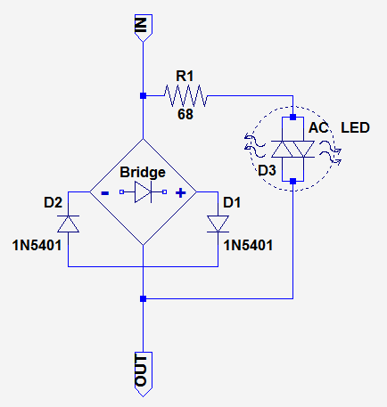
It will work, but its main drawback is its voltage drop, around 3V, translating into 2V rms: that is ~1% of the voltage in a 230V system, barely tolerable, and 2% for 120V: really problematic, and if the load takes a number of amperes, the dissipation will become an issue.
One of the 1N5401 could be omitted, but the control of the current in the LED would become acrobatic.
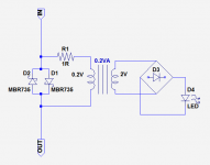
The circuit could be improved by adding a small transformer: in this case, a single pair of diodes is sufficient, and they can even be schottky's:
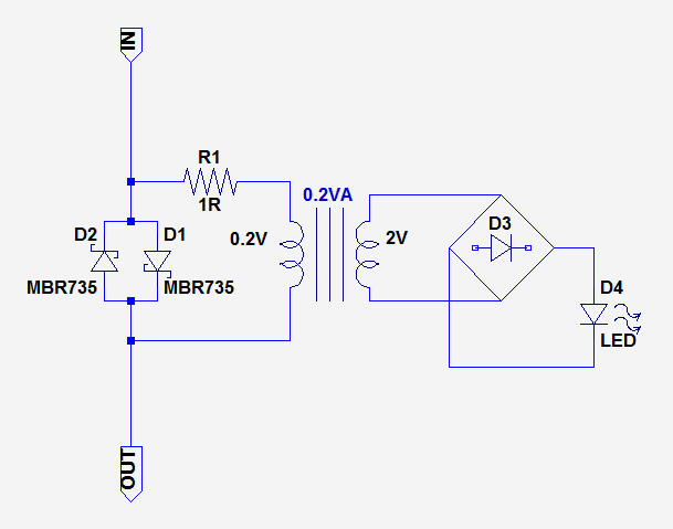
This solution neatly addresses the losses issue, but where are you going to find a 0.2V to 2V, 0.2VA transformer?
It will be a custom part, and a relatively bulky one: not very attractive.
A more attractive option is to resort to voltage multipliers: you can use the threshold voltage difference between ordinary and schottky diodes to obtain a sufficient yield:
It is a reasonable tradeoff between complexity and losses: typically less than 1V rms, and the components are off-the-shelf commodities, it is thus a possible and realistic option.
To be continued....
If taken literally, it looks impossible, except for EHV power lines.
In fact, such a pilot does require two wires, just like any other, but, unlike the regular ones like neons for example, they do not require both the neutral and phase to be present: they can be inserted anywhere in the wiring.
Why would you need such an arrangement?
There can be a number of reasons: access to the other wire can be downright impossible, unpractical or unsafe.
Examples of such situations are pumps with a built-in level sensor, heating elements with a built-in thermal switch, fans with a built-in humidity sensor, single-pole attic or cellar light-switches.
Sometimes, a regular pilot could be possible, but would require the butchering of an existing wiring, at great cost.
How does a single wire pilot work?
It drops a small voltage, and senses the presence of current in a circuit.
Ideally, such a pilot should be simple, reliable, inexpensive, it should work for a wide range of current, and perhaps the most important, it should be minimally intrusive, ie. drop a negligible voltage.
Conciliating all of these requirement is not easy, and eliminates some solutions first-hand, like shunt resistors or current transformers.
In order to cover a wide range of currents, a non-linear element is required, in practice two or more back-to-back diodes.
The dumbest of current sensor built according to these principles would look like this:
It will work, but its main drawback is its voltage drop, around 3V, translating into 2V rms: that is ~1% of the voltage in a 230V system, barely tolerable, and 2% for 120V: really problematic, and if the load takes a number of amperes, the dissipation will become an issue.
One of the 1N5401 could be omitted, but the control of the current in the LED would become acrobatic.
The circuit could be improved by adding a small transformer: in this case, a single pair of diodes is sufficient, and they can even be schottky's:
This solution neatly addresses the losses issue, but where are you going to find a 0.2V to 2V, 0.2VA transformer?
It will be a custom part, and a relatively bulky one: not very attractive.
A more attractive option is to resort to voltage multipliers: you can use the threshold voltage difference between ordinary and schottky diodes to obtain a sufficient yield:
It is a reasonable tradeoff between complexity and losses: typically less than 1V rms, and the components are off-the-shelf commodities, it is thus a possible and realistic option.
To be continued....
Attachments
I'm not sure I see a real problem to solve...
A true single wire detector w/LED AC live wire detector ~ Simple projects
I'd imagine you could desensitize the sensor with selecting a CMOS counter w/ a lower gain schmitt trigger input like a 4017. Reckon a strategic placed ferrite bead or resistor on the input wire could reduce stray or false detections . Or even attach a hall effect sensor for reduced impedance.
What if two diode drops in each direction is too much?
You could use just two diodes back-to-back, followed by many stages of voltage multipliers to drive the LED, but that's an uphill struggle: to begin with, the threshold difference between schottky and ordinary diodes is not huge, and each multiplier stage adds its own loss.
This means you end up with half a dozen schottky's and half a dozen big caps for a miserable result.
Fortunately, there are better options: converters. Unfortunately, true converters are either inductively coupled (Hartley type, think Joules thief) or driven (two stage, etc).
Using a custom wound component, Joule's thief style, or multiple transistors or a dedicated IC is not appealing, so what's the alternative?
It is possible to make a converter's substitute using an overdriven Colpitts oscillator.
It doesn't come near the alternatives regarding the boost ratio, efficiency or current output, but with high efficiency LEDs, it is quite sufficient, and requires only ordinary, off the shelf components.
Here is an example of pilot using such an oscillator:
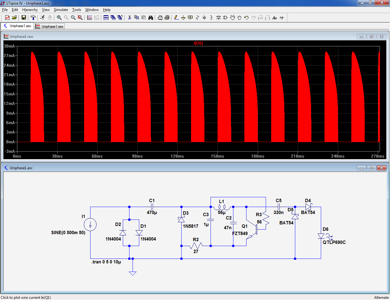
The transistor shown is a FZT or ZTX849, and a superbeta transistor does indeed work better, but alternatives like 2N6702 or 2SD571 are perfectly sufficient
You could use just two diodes back-to-back, followed by many stages of voltage multipliers to drive the LED, but that's an uphill struggle: to begin with, the threshold difference between schottky and ordinary diodes is not huge, and each multiplier stage adds its own loss.
This means you end up with half a dozen schottky's and half a dozen big caps for a miserable result.
Fortunately, there are better options: converters. Unfortunately, true converters are either inductively coupled (Hartley type, think Joules thief) or driven (two stage, etc).
Using a custom wound component, Joule's thief style, or multiple transistors or a dedicated IC is not appealing, so what's the alternative?
It is possible to make a converter's substitute using an overdriven Colpitts oscillator.
It doesn't come near the alternatives regarding the boost ratio, efficiency or current output, but with high efficiency LEDs, it is quite sufficient, and requires only ordinary, off the shelf components.
Here is an example of pilot using such an oscillator:
The transistor shown is a FZT or ZTX849, and a superbeta transistor does indeed work better, but alternatives like 2N6702 or 2SD571 are perfectly sufficient
Attachments
If you have an auxiliary supply like a 9V battery at your disposal, there is indeed no real problem to solve.I'm not sure I see a real problem to solve...
A true single wire detector w/LED AC live wire detector ~ Simple projects
I'd imagine you could desensitize the sensor with selecting a CMOS counter w/ a lower gain schmitt trigger input like a 4017. Reckon a strategic placed ferrite bead or resistor on the input wire could reduce stray or false detections . Or even attach a hall effect sensor for reduced impedance.
Since many people will find unpalatable the idea of hooking a battery somewhere inside an equipment just to feed a pilot light, I am examining alternative solutions.
A small solar cell panel with a rechargeable battery?If you have an auxiliary supply like a 9V battery at your disposal, there is indeed no real problem to solve.
Since many people will find unpalatable the idea of hooking a battery somewhere inside an equipment just to feed a pilot light, I am examining alternative solutions.
I still don't see a problem of using a small housekeeping power supply. Strange if this is truly fail safe , mission critical and youre working on an 'invasive' solution? Plus I'm not so sure folks would focus on an lil itty bitty LED.
I know this isn't you, but it reminds me of..>Often snake oil peddlers are inventing "a superfluous problem" to apply an "innovative" product. How about a wireless smart phone app. instead of a LED?
Last edited:
I think you've made your opinion: it is a useless solution looking for a non-existent problem.A small solar cell panel with a rechargeable battery?
I still don't see a problem of using a small housekeeping power supply. Strange if this is truly fail safe , mission critical and youre working on an 'invasive' solution? Plus I'm not so sure folks would focus on an lil itty bitty LED.
I know this isn't you, but it reminds me of..>Often snake oil peddlers are inventing "a superfluous problem" to apply an "innovative" product. How about a wireless smart phone app. instead of a LED?
This is fine by me, everyone is entitled to have its own opinion.
When I began developing the concept, several years ago, it was driven by my attic lighting: the switch had no pilot light, meaning the light would regularly be forgotten, and burn needlessly, sometimes for weeks before someone realizes.
The wiring inside the switch-box had no provision for hooking up a regular neon pilot, meaning I would have to lay a specific wire, pulled from another location.
I thought it was more elegant and less intrusive to keep everything in the condition, and add this small pilot in series with the switch.
It worked like charm, and this gave me the idea of applying the principle to other problems: you can for instance monitor the activity of such a pump:
An externally hosted image should be here but it was not working when we last tested it.
Or it can let you know when one of your PIR-activated light has "seen" something or someone:

etc, etc.
In fact, it is so convenient that I sometimes use it even when a regular wiring is possible. Why? It is simpler and faster.
Note that it is not limited to indication only: the LED can be an optocoupler and drive some management/control system.
Back to the subject.
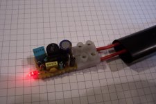
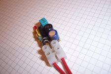
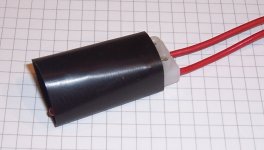
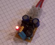
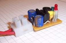
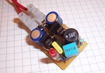
Here is an implementation example of the last circuit.
The LED color is preferably red, for forward voltage reasons. However, standard green or yellow remains possible, but not blue, white, etc.
PS: you will note that there is no "mission critical" in sight: it is just comfort and convenience
Attachments
Thanks Elvee for explaining your motivation.
Your attic wiring must be very old.
This can be a problem indeed, I have one of my multimeters that often eats 9V batteries due to me getting distracted. A timer based power switch w/ an override option is Flukes solution.
Neat solution for a mV boost converter. like.
Is the oscillators decay time improved from the simulation by more modern efficient LED loading?
I reckon at some load power and at higher ambient T the 1A diodes will need to be upgraded.
If you are thinking about a small transformer, why no use a small current transformer?
Or the smallest toroid you can find?
This was my 1st thought too..
Current transformers have volt*second constraints so the secondary voltage must remain small due to small core and low mains frequencies. Something reasonably sized for cost will have voltages perhaps less than a forward drop of PN junction diode. Although there is no requirement to keep the transformer linear so it might be 2-3 times higher Volts*sec than spec.
Last edited:
The $3 parts from Triad are rated 4V on the secondary, at power frequency. Ratios from 1:17 (1A) to 1:500 (30A). Some thought needed to match a V-limited current output to a steady-V max-current load, but I think an answer is in reach.
Current Transformers, 50-60Hz, cheapest first
I too have dabbled with "sneak power lights". I want more light switches in cellar and garage. Without more Code-legal wiring. That's not hard. But it can be DARK in there. I want the switches to light-up. My 1940 solution is a LV power source, a mechanical ratchet relay, and switches. The Y2K add-on is a 5mA LED in/by each switch. Several such sneak paths will not pull-in the 100mA relay. The light goes out when you pres the button, but you already found it. The light stays on while the main lights are on, the sub-Watt waste is affordable.
The $3 parts from Triad are rated 4V on the secondary, at power frequency.
wow nice find! Triads data sheet indicates a born on date of 2016> perhaps a gapped steel core? Safety approvals, yup.
Pays to look beyond Coilcraft.
Last edited:
I've used a switch that has a small neon light inside. A solution of the 60s.
Cannot be simpler, but works in a negative logic.
Neon light ON means OK, the cellar light is OFF.
Other, solution, I could use. I have a multimeter that detects live wires inside walls. This feature works wether the meter is on or off.
It has a 9V battery inside, while off it is actually stand by with a negligible current draw.
It is puzzling to see the red light flashing while the multimeter is off. Well, that is how it is.
Here you have a no contact pilot light.
Very nice find indeed, compact and inexpensive, and the 1:16.6 one is practically the same as the one I indicated here:The $3 parts from Triad are rated 4V on the secondary, at power frequency. Ratios from 1:17 (1A) to 1:500 (30A). Some thought needed to match a V-limited current output to a steady-V max-current load, but I think an answer is in reach.
Current Transformers, 50-60Hz, cheapest first
0.25VA and a ratio a bit larger, but it's not critical at all.
Since the secondary is isolated, the LED could be located remotely using low voltage wiring.
I had looked for such a part years ago, but the size and cost were horrendous.
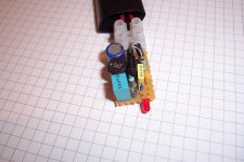
For places wher space is very limited (like inside a switch), the electronic version would still have its place: even with TTH components mounted on a perfboard, the volume is ~half of the transformer, and with SMD components, it could be lodged inside the body of a neon pilot for example.
The previous variant contented itself with one diode drop in each direction, but the diodes had to be ordinary silicon, to allow the indicating oscillator to start.
Schottky diodes would reduce the losses further, but how could they be compatible with a silicon-based oscillator?
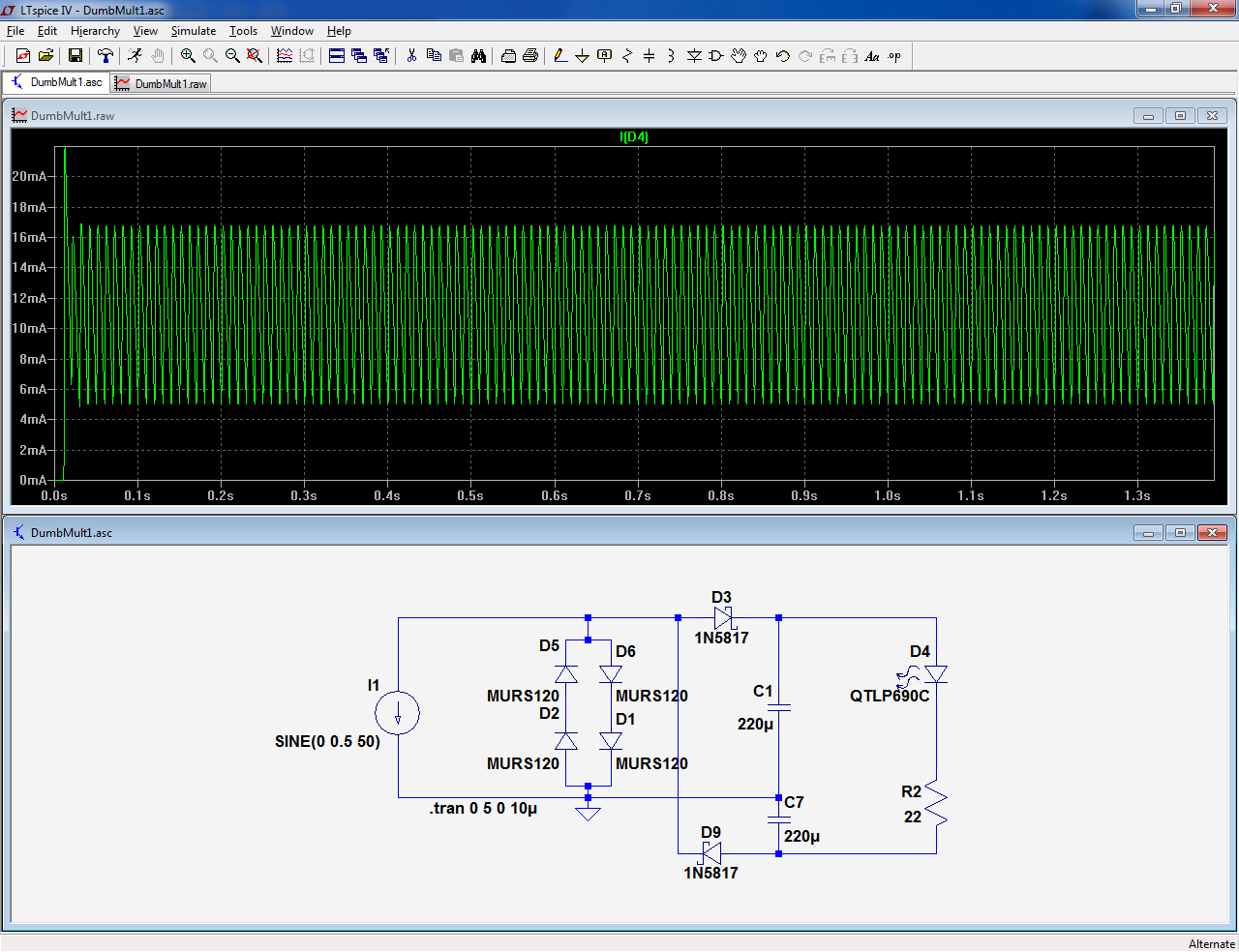
This circuit generates two polarities, and uses the opposite polarity to generate the drive to synchronous rectifiers.
Once the circuit has started, its operation is obviously possible, but how can it start?
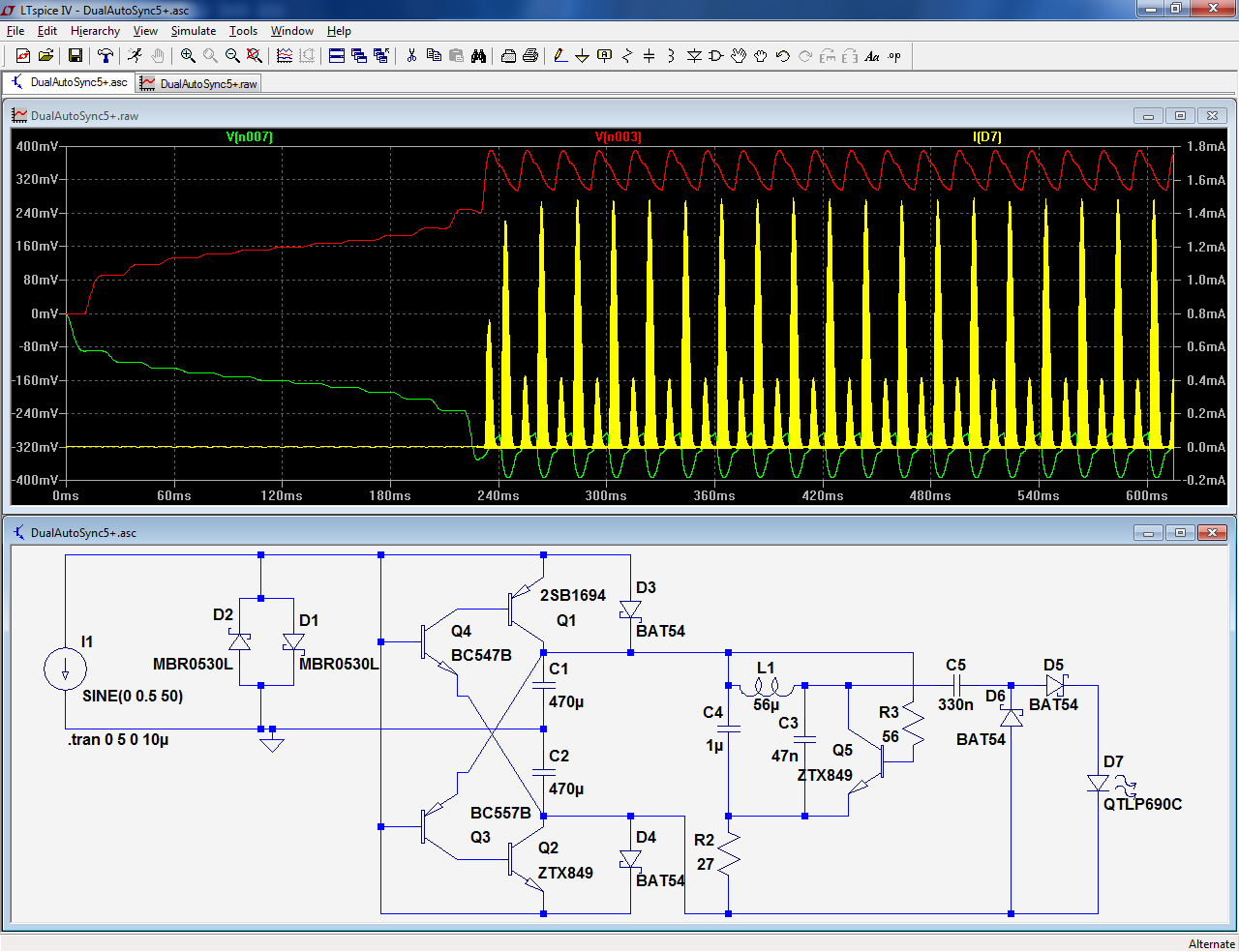
Small schottky's D3 and D4 "prime" the circuit, by allowing a small voltage to appear across the filter capacitors, then a regenerative process begins, with each output voltage gaining more and more strength at each cycle, until full lock-in happens (red and green traces).
The Vbe is a purely fictitious notion, and can become arbitrary low for very currents, which is illustrated here.
All the detectors described will operate from a few tens of mA up to twice the If max of the diodes used as a shunt.
If a threshold is desired, to make the distinction between the active and standby conditions for example, the diodes should be shunted by a suitable resistor
Schottky diodes would reduce the losses further, but how could they be compatible with a silicon-based oscillator?
This circuit generates two polarities, and uses the opposite polarity to generate the drive to synchronous rectifiers.
Once the circuit has started, its operation is obviously possible, but how can it start?
Small schottky's D3 and D4 "prime" the circuit, by allowing a small voltage to appear across the filter capacitors, then a regenerative process begins, with each output voltage gaining more and more strength at each cycle, until full lock-in happens (red and green traces).
The Vbe is a purely fictitious notion, and can become arbitrary low for very currents, which is illustrated here.
All the detectors described will operate from a few tens of mA up to twice the If max of the diodes used as a shunt.
If a threshold is desired, to make the distinction between the active and standby conditions for example, the diodes should be shunted by a suitable resistor
Attachments
One last word of caution: if any of the above circuits is used for mains applications, you need to observe all the relevant precautions: good construction practices, proper insulation and distances, etc.
This also applies to the transformer based one: all of the primary side will be live, and without precautions, the secondary also has to be treated as such, even if the transformer has the required certifications.
Note that LEDs do not provide safety insulation: they cannot be inserted directly into a metal front-panel, there has to be some kind of additional insulation; the best technique is indirect lighting, through translucency.
The light output with high efficiency LEDs is sufficient for that.
Sure, but is it going to cost less than 2€/unit price (very much less in quantity), occupy less than 5cm³ (very much less with SMD components), operate from 20mA to several amperes with a near-constant brightness?How easy can it be.
Sometimes, simplicity can be costly
- Status
- This old topic is closed. If you want to reopen this topic, contact a moderator using the "Report Post" button.
- Home
- Amplifiers
- Power Supplies
- Single wire pilot lights