Hi to u all,
with reference to a voltage doubler ,what are the voltages on the right and left plates of the input capacitor when the input waveform goes negative for ,say -10volts?The first diode is said to be conducting at that time.Does it mean that its anode voltage is less negative than its cathode?eagerly waiting your explanations to help me understand the basics of what appears to be such a simple circuit.you would not perhaps believe me but i find the working of enhancement mosfets easier to grasp than this latter circuit.
with reference to a voltage doubler ,what are the voltages on the right and left plates of the input capacitor when the input waveform goes negative for ,say -10volts?The first diode is said to be conducting at that time.Does it mean that its anode voltage is less negative than its cathode?eagerly waiting your explanations to help me understand the basics of what appears to be such a simple circuit.you would not perhaps believe me but i find the working of enhancement mosfets easier to grasp than this latter circuit.

....what are the voltages on the right and left plates of the input capacitor when the input waveform goes negative for ,say -10volts?....
Are you asking about the polarity of the input cap voltage?
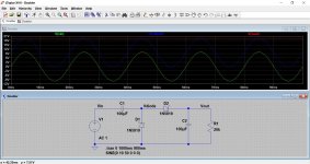
Oddly (and not noted in any book I've seen), the input cap can start the "wrong way" for its final polarity. On the first half-cycle, the two caps split the input voltage. So 5V on each. But the first cap gets a -reverse- voltage from what it will assume after another cycle. Then when the input swings negative, and the first diode clamps to zero V, the left end of the cap is negative of the right end.
With film caps we would not care. But doublers almost always want electrolytics for cost reasons. Electros will conduct in the reverse direction (so the sim below is flawed). I think we get away with it because we invariably use quite large cans, and the reverse voltage and current surge is very short.
Attachments
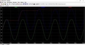
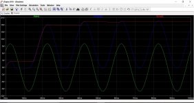
Here's a run with simulated electro-cap back-leakage. D28 R140 give a ~~0.7V threshold and some DCR.
For this case we have about 1.5V and 1.5A for less than a half-cycle. The 2 Watt transient is not enough to heat any cap we would use. Without destructive heat, back-leakage is not destructive to electros. (Large wet ones have been used as transient clamps and as rectifiers.)
For this case we have about 1.5V and 1.5A for less than a half-cycle. The 2 Watt transient is not enough to heat any cap we would use. Without destructive heat, back-leakage is not destructive to electros. (Large wet ones have been used as transient clamps and as rectifiers.)
Attachments
Last edited:
...increasing the input to filter cap ratio stops that effect.
Seems to me (my sim is tired) that the ratio changes the % of input voltage that the input cap gets, but won't reduce to zero.
The input cap is "logically" larger than the smoothing cap, because it is series and at a lower-V higher-I point of the circuit. Of course many odd values can "work".
Changing the turn-on point on the input wave (we don't have zero-cross detectors in our switch-fingers) gives other details of start-up.
As millions of these things were built and worked for years, before simulators, I'm inclined to think it is No Big Deal.

..."SPICE" the delon....
Why?
It just works.
No funny-business.
Values can be guessed.
It is full-wave on the input, full-wave on the total output.
It gives a solid half-voltage for when you want >400V total supply.
It was "the" hot trick for new tube amp designs in the mid-1960s, when diodes still cost something. Bogen used it dozens of times, even up to the big 2x150W beast.
You can "spice it" in Duncan.
me> Bogen...
Download Schematics For Free here at makearadio.com!
http://makearadio.com/schematics/images/bogen-chb10a-4.jpg
http://makearadio.com/schematics/images/bogen-chb35a-6.jpg
http://makearadio.com/schematics/images/bogen-chb50-6.jpg
http://makearadio.com/schematics/images/bogen-chb100b-6.jpg
http://makearadio.com/schematics/images/bogen-m60a-8.jpg
http://makearadio.com/schematics/images/bogen-m120-7.jpg
http://makearadio.com/schematics/images/bogen-m330a-8.jpg
http://makearadio.com/schematics/images/bogen-mo100a-7.jpg
http://makearadio.com/schematics/images/bogen-mo200a-7.jpg
Voltage doubler 2
Hi to u all,
The circuit i am talking about is that of mr Greinacker.I am really interested to know what happens at the instant the input voltage goes negative to both the input capacitor and the first(shunt?)diode .if at that instant the input cap is discharged,the voltage at the cathode of the diode is negative.does it mean that the voltage on the anode is less negative so that the diode gets into forward bias to charge the right plate to a positive charge.Is my reasoning correct or i am getting it all wrong?The subject is getting into physics theory.
Voltage doubler 3
Hi to u all,
Thanks to u all for your explanations and simulations of the voltage doubler circuit.now i understand it better after perusing through your posts.The key to comprehend the circuit is to know the behaviour of the capacitor as it "faces" the peak neg. Voltage it is subjected to.
Hi to u all,
Thanks to u all for your explanations and simulations of the voltage doubler circuit.now i understand it better after perusing through your posts.The key to comprehend the circuit is to know the behaviour of the capacitor as it "faces" the peak neg. Voltage it is subjected to.
This is a common voltage doubler I use:
An externally hosted image should be here but it was not working when we last tested it.
- Status
- This old topic is closed. If you want to reopen this topic, contact a moderator using the "Report Post" button.
- Home
- Amplifiers
- Power Supplies
- voltage doubler