Oscilloscopes are connected to earth ground so not easily done. Safety first, I'd advise you to not even attempt it. A transformer would filter out some of the noise, and anyway it's the secondary side where any remaining noise might get into the equipment so there is no real need to measure the mains itself
Felipe, have you 'observed' a problem that you think is noise from the mains? Or do you want to attenuate a certain type of noise because you are second guessing a problem?
As you may appreciate, the mains is easily seen to not be just a pure sine wave voltage source. An oscilloscope, or even better a spectrum analyser, can easily show that on the secondary of a transformer, but that technique has a low pass filter characteristic.
As you may appreciate, the mains is easily seen to not be just a pure sine wave voltage source. An oscilloscope, or even better a spectrum analyser, can easily show that on the secondary of a transformer, but that technique has a low pass filter characteristic.
Mains transformers are not ideal for that purpose: they degrade the frequency response above a few kHz, and distort (a little) lower frequencies.Thank you, I have Toroidal, R-Core & EI.
Something more?
In general, disturbances are high frequency, which means you can get away with some short-cuts.
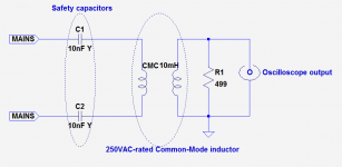
One is to use a common-mode choke intended for mains purposes coupled with "Y" capacitors.
This will result in a second order high-pass filter, useful for removing high amplitude, low-frequency voltages, and will provide a double insulation barrier for safety: one is not completely regular, because X-rated components should not be used for Y applications (unless they are certified for both, which is not uncommon), and the other, Y caps, are OK, but on their own cause earth leakage which can be annoying for metrological applications.
If your test gear is earthed, this setup is completely safe, if properly built, of course.
If you have doubts, ask the necessary explanations, don't risk your life.
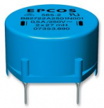
A CMC looks like this:
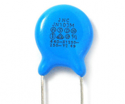
A Y capacitor looks like this:
Be sure to respect a good safety distance (>15mm) between the mains side and the measurement side.
If you want to look at low to medium frequency distortions (up to 1MHz), this probe is a safe option:
A safe and inexpensive probe for direct mains measurements
The frequency ranges of these two solutions overlap, but the opamp probe does not remove the LF contents, which might obscure the fine HF details of the perturbations
Attachments
Oscilloscopes are connected to earth ground so not easily done. Safety first, I'd advise you to not even attempt it.
None of my scopes are grounded. One is an old 2 prong heathkit. One is USB and connected to a laptop, and the other is a miniDSO with a battery and LCD screen.
")
If it won't go through a transformer to a 'scope, it won't go through a power transformer to your gear. There's no strong need for a super transformer.
IMHO, the power supply's main job is to take whatever junk you get and turn it into clean DC. Very ordinary techniques work for almost all utility power.
Crud above 10KHz is cheap to reduce, so may be filtered just-in-case.
A tube amp output transformer has good bandwidth. 15 Watts at 5K is 250V, so pick one bigger than this.
You can infer a LOT about possible line-crap by listening to what it seems to do to your sound.
I too would like to know just why you want to see the line wave.
If you use a pair of standard oscilloscope probes at 10/1 as a differential input with series capacitors of 1 nF 1000V you can safely look at the AC line.
Even if you touch the AC line after the isolation capacitors that is less than 50 micro amps of current. Well below leathal but probably enough to be educational.
Now if you want to feed a spectrum analyzer you can use capacitors feeding a voltage divider into a wide band instrumentation amplifier.
The important issue to have a high enough input impedance that the capacitor coupling will provide a high level of isolation.
Lethal current can start at 5 mA, a theory I was taught but never have tested. Normally a safety factor of 10 would be applied, but as you can do 100 quite easily that is where I would aim. Keep in mind even with a transformer has leakage capacitance.
I would also suggest you build a box to contain all the high voltage parts to maintain safety.
Of course the other method is to use an oscilloscope that is designed to measure power line distortion like the Tektronix THS735.
You can also use a spectrum analyzer instead of an oscilloscope, you will see the frequency-domain aspect, which can be instructive too, but with the probe I suggested, you will need to add a good surge protection, because it will pass any voltage spike unattenuated, quite sufficient to kill an input.
Oscilloscopes are much better protected, and can be connected directly.
Protection network could be made of two string of 5 1N4148's connected back-to-back
Oscilloscopes are much better protected, and can be connected directly.
Protection network could be made of two string of 5 1N4148's connected back-to-back
Felipe, it sounds like you are on a fishing expediton, or a journey of enlightenment, rather than trying to track down a problem issue?
What scope do you have? Does it have spectrum analyser processing?
You can also use a soundcard to observe the mains voltage (same safety provisos as an oscilloscope) - there are many free spectrum analyser softwares available, and you will then see any periodic or capturable noise signals down to below -100dB over a pretty good frequency range (depending on your soundcard, but at least out to 20kHz with the simplest). A laptop, or a USB isolator, can provide additional peace of mind if your ability to make a safe probing configuration is a little suspect.
If you use a pair of standard oscilloscope probes at 10/1 as a differential input with series capacitors of 1 nF 1000V you can safely look at the AC line.
Now if you want to feed a spectrum analyzer you can use capacitors feeding a voltage divider into a wide band instrumentation amplifier.
Of course the other method is to use an oscilloscope that is designed to measure power line distortion like the Tektronix THS735.
I guess using the two probes with my dual trace scope: one for Line & the other one for Neutral?
Could you elaborate about the voltage divider, I don't have spectrum analyzer , I will use software (please advice free & good if possible) & the internal soundcard of my PC?
Tektronix THS735 is very expensive for my pocket.
You can also use a spectrum analyzer instead of an oscilloscope, you will see the frequency-domain aspect, which can be instructive too, but with the probe I suggested, you will need to add a good surge protection, because it will pass any voltage spike unattenuated, quite sufficient to kill an input.
Oscilloscopes are much better protected, and can be connected directly.
Protection network could be made of two string of 5 1N4148's connected back-to-back
Protection network as attached image? Where to place: between the filter & the probe?
Felipe, it sounds like you are on a fishing expediton, or a journey of enlightenment, rather than trying to track down a problem issue?
What scope do you have? Does it have spectrum analyser processing?
You can also use a soundcard to observe the mains voltage (same safety provisos as an oscilloscope) - there are many free spectrum analyser softwares available, and you will then see any periodic or capturable noise signals down to below -100dB over a pretty good frequency range (depending on your soundcard, but at least out to 20kHz with the simplest). A laptop, or a USB isolator, can provide additional peace of mind if your ability to make a safe probing configuration is a little suspect.
Yes it's a fishing expedition mixed with a lot of curiosity rather than a problem issue I think, let's see finally the measurements...
Scope is an old Hameg Dual Trace HM-412-5 of course without spectrum analyzer.
Do you know a free spectrum analyser software available & reliable?
TIA guys for all great support really appreciated.
Felipe
Attachments
![WP_20171212_003[1].jpg](/community/data/attachments/608/608262-993b8abf49e5faee462302e2bee09879.jpg)
Last edited:
In parallel with the analyzer's inputProtection network as attached image? Where to place: between the filter & the probe?
- Status
- This old topic is closed. If you want to reopen this topic, contact a moderator using the "Report Post" button.
- Home
- Amplifiers
- Power Supplies
- How measure safely AC mains pollution noise