I bougth a BMS protection on ebay for the lifepo4 3,3v battery buffer. It should increase the output impedance. I will see if it impacts SQ.
I wanted to use the low charge protection of the 6,4 upstream battery (it cuts at 4,5v), but the lm317 cuts first if the upstream voltage is too low and the 6,4v battery never switch of ...
The other problem is that if i forget to switch off the 3,3v battery, even if there is a BMS protection at two votls, it will takes half an hour to reach 3,3v for my mfc to restat when i wan to use it.
I could use zener diods to trigger a relay switch after the 6,4v but i head they are noisy ...
Last edited:
Hi
May be you can help me.
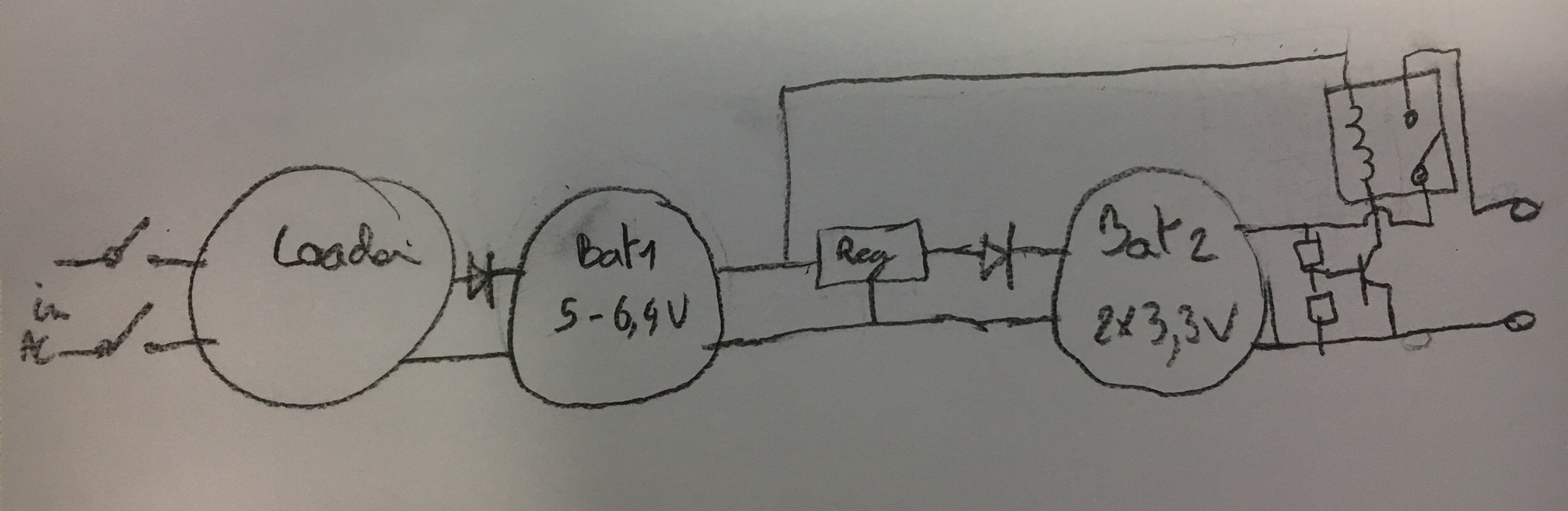
So i have Lifepo4 6,4V >> switch >> LM317 (3,3V) >> 2X3,3V lifepo>> Diods >> 3,04V
The lifepo4 6,4V cuts with its BMS at 4,5V
I wanted to add a relay after the 6,4V battery (parallel to it) to trigger the final 3,04V output when the switch is of of 6,4V cutted by its BMS.
The problem is that even when Lifepo4 6,4V is switched of, i have a voltage on the LM317 input coming from the 3,3V buffer that switch my relay on.
I there a solution for trigger this relay only when my lifepo4 6,4V is on ?
Thank you
Bernard
May be you can help me.
So i have Lifepo4 6,4V >> switch >> LM317 (3,3V) >> 2X3,3V lifepo>> Diods >> 3,04V
The lifepo4 6,4V cuts with its BMS at 4,5V
I wanted to add a relay after the 6,4V battery (parallel to it) to trigger the final 3,04V output when the switch is of of 6,4V cutted by its BMS.
The problem is that even when Lifepo4 6,4V is switched of, i have a voltage on the LM317 input coming from the 3,3V buffer that switch my relay on.
I there a solution for trigger this relay only when my lifepo4 6,4V is on ?
Thank you
Bernard
I think i got something theorically working (i will post a draw).
I will trigger an output relay on/off with a 2N222 sensor if output lifepo4 voltages is too low in case i forget to switch off.
A have a last problem to solve : the SQ is very good with a LM317 upstream by lifepo4 3,3V buffer, but voltage dropout is to high (3V), my upstream battery is 6,4V and dowstream buffer 3,3V. I tried a LT1086 (1,5A, 1,3V drop out) instead of LM317 but the sound is not so good i don't now why.
Are they other LDO i could try ? I need 1,5A to be confortable and not more than 2V drop out.
Or something i could do for LT1086 ? try a LT1085 that is 3A ?
B.
Here is the target below.
for the regulator, i think the SQ is linked to the ringing with the digital target (there is no regulator in the MFC, just a LC filter and a barrier diod on the input).
As the amount of noise to my digital chain is very low with the lifepo4 alone, i assume that the very low output impedance of the lifepo4 manages the fast transient for the digital pcb ; so maybe i need a LOW transient LDO for floating charge, with a low ringing. Am i wrong with this approach ?
Attachments
Bonjour Bernard,
If you'll allow me to first draw a bit on my experiences with batteries & LiFePO4 types ...
I float charge mine (A123 26650) at 3.405 VDC, however, they can be float charged also at 3.3 VDC - I'm not sure there will be any sound difference as I remember reading that their electrical characteristics are quite identical at most all of their charge states.
Regarding your schematic I personally would say that I don't think you really gain anything by having two batteries in series. Not least since the regulator is in-between the batteries (and the LM317 actually is quite noisy).
Also, using the diodes makes for a very crude voltage regulation which - depending on how your MFC is designed - may lead to slightly varying sound quality from the MFC due to slightly different supply voltages. I would omit the diodes.
If it were me I would look at e.g. the LT3045 which is capable of 0.5 A charging current (and is parallelable for higher current needs), AND has an enable/disable pin which can switch on/off the LT3045. Thus you can decide if it is to charge or "just be there" virtually without any influence on the circuitry. If e.g. the small pins are an issue you might find a suitable regulator on e.g. analog.com or Linear Technology's webpages. If you would like one with a shutdown feature (disable) look for that.
Then I would use a tlc555 timer (CMOS version) - set to the typical listening time you like - and use the output of this timer to switch on or off the LT3045(s) AND - if you really want it quiet - an optional relay before the LT3045/other regulator. Thus, when the tlc555 completes its timing period it switches on both the relay leading to the LT3045, and enables the LT3045.
A probably quite fine alternative is to just have the tlc555 switch on/off a relay leading to the LT3045 and then the lt3045 will only be active when the relay supplies power to this regulator. It would be the simplest way of doing it, I guess - remember that the relay should be able to handle the peak current charging the capacitor on the input of the LT3045 (or some other regulator).
The LT3045 sinks a maximum of 25 uA (reverse output current, p. 4 in the datasheet) when not on/used so you can calculate how long you can have your batteries connected to it without depleting them when not charging.
You may slow down the LT3045's regulation speed by adding a resistor between the point where the 10uF capacitor is connected and the PGFB resistors in the LT3045 internal schematic on p.1 of the datasheet. This will increase the effective output impedance and thus make an R/C filter with the capacitances in the MFC.
Now, this is the slightly ambitious solution ... And I don't know if it suits your skill level.
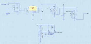
In case it is outside of what you would like I may suggest you continue using the LM317T. A structure could be like this:
AC input -> relay controlled by tlc555 or some other timing unit -> LM317T -> battery.
If the timing is correct the only risk I can see in this is if you some day switch off your AC wall supply ... so that the resistors on the output of the LM317T drains the battery. It does take some time though for this to happen (if e.g. 2000 mAH capacity of the battery 2000/5 = 400 hours or ~ 16 days.)
Another possibly even simpler solution could be to use a schmitt triggered inverter circuitry to control a relay so that the sequence is:
battery -> relay -> MFC
I have included a schematic with a couple of building blocks (e.g. the schmitt trigger circuitry) which you can move around and combine as you see fit.
BTW - remember to put a diode across the relay (correct polarisation") ) so that the current peak when the relay switches off does not blow the inverter (or transistor)!
) so that the current peak when the relay switches off does not blow the inverter (or transistor)!
Hope this may help - & good luck in finding your solution.
Cheers,
Jesper
P.S.: There should be a resistor (~ 33 ohms) on the "relay on/off" output from the last schmitt trigger inverter.
If you'll allow me to first draw a bit on my experiences with batteries & LiFePO4 types ...
I float charge mine (A123 26650) at 3.405 VDC, however, they can be float charged also at 3.3 VDC - I'm not sure there will be any sound difference as I remember reading that their electrical characteristics are quite identical at most all of their charge states.
Regarding your schematic I personally would say that I don't think you really gain anything by having two batteries in series. Not least since the regulator is in-between the batteries (and the LM317 actually is quite noisy).
Also, using the diodes makes for a very crude voltage regulation which - depending on how your MFC is designed - may lead to slightly varying sound quality from the MFC due to slightly different supply voltages. I would omit the diodes.
If it were me I would look at e.g. the LT3045 which is capable of 0.5 A charging current (and is parallelable for higher current needs), AND has an enable/disable pin which can switch on/off the LT3045. Thus you can decide if it is to charge or "just be there" virtually without any influence on the circuitry. If e.g. the small pins are an issue you might find a suitable regulator on e.g. analog.com or Linear Technology's webpages. If you would like one with a shutdown feature (disable) look for that.
Then I would use a tlc555 timer (CMOS version) - set to the typical listening time you like - and use the output of this timer to switch on or off the LT3045(s) AND - if you really want it quiet - an optional relay before the LT3045/other regulator. Thus, when the tlc555 completes its timing period it switches on both the relay leading to the LT3045, and enables the LT3045.
A probably quite fine alternative is to just have the tlc555 switch on/off a relay leading to the LT3045 and then the lt3045 will only be active when the relay supplies power to this regulator. It would be the simplest way of doing it, I guess - remember that the relay should be able to handle the peak current charging the capacitor on the input of the LT3045 (or some other regulator).
The LT3045 sinks a maximum of 25 uA (reverse output current, p. 4 in the datasheet) when not on/used so you can calculate how long you can have your batteries connected to it without depleting them when not charging.
so maybe i need a LOW transient LDO for floating charge, with a low ringing. Am i wrong with this approach ?
You may slow down the LT3045's regulation speed by adding a resistor between the point where the 10uF capacitor is connected and the PGFB resistors in the LT3045 internal schematic on p.1 of the datasheet. This will increase the effective output impedance and thus make an R/C filter with the capacitances in the MFC.
Now, this is the slightly ambitious solution ... And I don't know if it suits your skill level.
In case it is outside of what you would like I may suggest you continue using the LM317T. A structure could be like this:
AC input -> relay controlled by tlc555 or some other timing unit -> LM317T -> battery.
If the timing is correct the only risk I can see in this is if you some day switch off your AC wall supply ... so that the resistors on the output of the LM317T drains the battery. It does take some time though for this to happen (if e.g. 2000 mAH capacity of the battery 2000/5 = 400 hours or ~ 16 days.)
Another possibly even simpler solution could be to use a schmitt triggered inverter circuitry to control a relay so that the sequence is:
battery -> relay -> MFC
I have included a schematic with a couple of building blocks (e.g. the schmitt trigger circuitry) which you can move around and combine as you see fit.
BTW - remember to put a diode across the relay (correct polarisation
) so that the current peak when the relay switches off does not blow the inverter (or transistor)! Hope this may help - & good luck in finding your solution.
Cheers,
Jesper
P.S.: There should be a resistor (~ 33 ohms) on the "relay on/off" output from the last schmitt trigger inverter.
Attachments
Last edited:
Hi
Thank you Gentlevoice for your advices.
There is no way that i connect the lifepo4 to AC (except of course for load). One of the goal to this supply is AC decoupling. I disconnect all the wires (neutral, phase and ground) when the supply is working. I found a huge impact on SQ with this.
The other impact is the very low noise of those batteries. I have made a lots of new listenning tests, and i am getting back from the regulator solution : i test LM317, LT1086 and TPS7A4700 and at the end none of them beats the lifepo4 alone.
About the LT304, it outputs 0,5 V and my MFC is more the 1A, so that the voltage will not be constant and it lost its interest.
Those lifepo4 batteries really sucks the noise of the digital devices. I thought it was because of the ultra low impedance but i am not sure now because it works too with my dropout diods that increase the outptut impedance (aren't they ?).
I test now 4 X 3,2v cells in parrallel. because the more there are, the more the voltage stability is long : with 1A out, they stay two hours between 3,19 <> 3,21 v. So considering the good voltage for my MFC is between 3V and 3,19V (and with a small voltage dropout), i am ok for hours ...
I got this dropout problem. I need without regulator an ideal 0,15v dropoff and i get 0,22 for the lowest dropout diod given to 0,21V (with two in parrallel). I will try more in parrellel but i am not sure it will change something. Would there be other solution for this 0,15V dropout without increase the impedance on use a regulator ?
thank you for the circuit you put in attachment.
question : Is the advantage of the 74VHC14 the very low curent leak compare to a 2N222 or other transistor ?
About the relay management : how do you wake up the lifepo4 once the two relays are off because of a low voltage ?? other problem is that the 74VHC14 has a 40ma output, it is low for a relay self no ?
I was planning to use a sensor + relay on the ouptut size, and a BMS PCB (4$ on ebay or aliexpress) to manage the leaks into the loader, i think they have wake up recovery mode once they are in security mode.
Timer is a good solution to go to sleep without having to switch off the MFC...
I think i will have : a mecanical switch for :
- play
- lifepo4 completely isolated (for long no-use time))
- Load mode
+ a voltage relay switch off on the output (if i forget to switch off the MFC), the leaks into the loader if it is pluggeg but off, managed by the BMS circuit.
If someone would have an id for the 0,15v low impedance drop out it would be realy nice (i would win 3 hours listening duration) ...
Bernard
Hi Bernard,
Just a brief reply ...
No, the potential advantage of the 74VHC14 is that it is either on or off. Thus, if the battery voltage changes only very little over time - if using a transistor with a limited Hfe - the relay may only partially be switched on or off, and this may wear the relay as well as lead to the relay contacts having high impedance (i.e. a bad connection).
A disadvantage of the 74VHC14 may be that it has some hysteresis, i.e. there is an input voltage span between the 74... output going low or high. This input voltage span may be too big for your desired battery voltage swing - you can see what the span is in the datasheet. If you want to make a smaller battery voltage swing on the batteries cause the 74... to shift between high or low position, you might add a small transistor amplifier prior to the 74... Thus a small battery voltage swing may cause the 74... to shift between high and low positions. Also, the 74VHC14 is a so-called Schmitt trigger device meaning that it will not oscillate at a very high frequency if the input voltage is close to where it shifts between the high or low states.
Anyway, I think these were my ideas, except if it were me I would investigate if the MFC could actually handle 3.4 volts. It would give a higher battery capacity (closer to full charge), and thus longer use time.
Good luck with your endeavors
Jesper
Just a brief reply ...
question : Is the advantage of the 74VHC14 the very low curent leak compare to a 2N222 or other transistor ?
No, the potential advantage of the 74VHC14 is that it is either on or off. Thus, if the battery voltage changes only very little over time - if using a transistor with a limited Hfe - the relay may only partially be switched on or off, and this may wear the relay as well as lead to the relay contacts having high impedance (i.e. a bad connection).
A disadvantage of the 74VHC14 may be that it has some hysteresis, i.e. there is an input voltage span between the 74... output going low or high. This input voltage span may be too big for your desired battery voltage swing - you can see what the span is in the datasheet. If you want to make a smaller battery voltage swing on the batteries cause the 74... to shift between high or low position, you might add a small transistor amplifier prior to the 74... Thus a small battery voltage swing may cause the 74... to shift between high and low positions. Also, the 74VHC14 is a so-called Schmitt trigger device meaning that it will not oscillate at a very high frequency if the input voltage is close to where it shifts between the high or low states.
Anyway, I think these were my ideas, except if it were me I would investigate if the MFC could actually handle 3.4 volts. It would give a higher battery capacity (closer to full charge), and thus longer use time.
Good luck with your endeavors
Jesper
- Status
- This old topic is closed. If you want to reopen this topic, contact a moderator using the "Report Post" button.
- Home
- Amplifiers
- Power Supplies
- Battery DC converter