Here are a few examples (non exhaustive) of a very useful type of accessory: battery timers.
I have noticed a curious paradox: I have a lot of battery-operated instruments and testers, both commercial and home-brew, and the biggest battery-eaters are the ones that I use less frequently.
The explanation is simple: when I use an instrument, I sometimes forget to switch it off.
If the instrument is used daily, I notice the situation the next day, when the battery hasn't yet had time to drain out.
If it is used once a month, the battery invariably ends up completely flat.
Some instruments are already fitted with some kind of timer, but others aren't, and it is a good idea to equip them too, with simple, cheap and versatile circuits.
The timer can be "plain vanilla", with just a button to start the timer.
An example of such a timer is used in this project:
http://www.diyaudio.com/forums/power-supplies/303629-windings-phase-finder-aka-phasedots-tester.html
Here, it is implemented in discrete form, but many other options exist of course.
A smarter type of timer will also take charge of the power on/off function, eliminating the need for a standard power switch.
Here are three examples of such a combination:
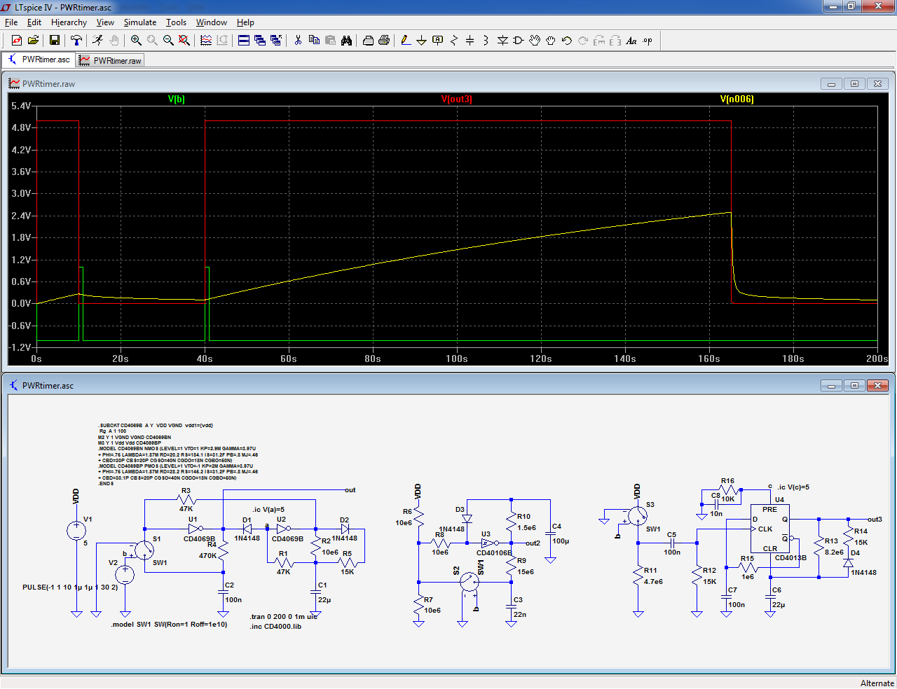
The first uses two inverting gates; here, they are just inverters, but NAND, NOR or XOR operators, buffered or unbuffered can also work.
The circuit accept regular and schmitt-trigger inputs.
For U2, a schmitt function is preferable to reduce the current consumption during certain phases of the timing, but the circuit remains completely functional with normal gates.
In the OFF condition, the consumption is ~0: just the leakage current of the CMOS IC, typically less than 1nA.
S1 symbolizes the push-button. Its debouncing time-constant is determined by R4-C2.
The time-out delay is set by R2-C1.
The second example uses a single, schmitt-trigger gate. It does have a drawback though: in the OFF state, a small current is consumed by the divider R6-R7: around 500nA.
This may or may not be a problem.
The third example is based on a flip-flop. the deboucing is ensured by C5, R11, R12 and R15, C7.
Note that R16 and C8 must not be implemented: they are used to force the sim to start in well-defined conditions.
R13 and C6 set the main time-constant.
This one also has ~zero consumption when OFF
All three circuits have time delay of ~120s, 2 minutes. This can be easily adapted, from seconds to perhaps ~10 minutes. Going higher with standard components would be unreasonable.
All three circuits have an active high output: they could control a NMOS in the negative line.
They can easily be converted to active low: in the two gate-equipped ones, one just needs to reverse the diodes and in the FF one, Q/ would become the output.
The waveforms shown apply to the FF version.
Note that these are just examples, many variations are possible. In general, it is possible to use left-over logic operators, but if you do that, you have to take care that the other operators do not try to impose a high level into the unpowered part of the circuit, as this will lead to abnormal current consumption
Note that the second circuit does not work properly in sim: the CD40106 model is faulty, and has a 20nA input leakage, but the real circuit works perfectly.
I have noticed a curious paradox: I have a lot of battery-operated instruments and testers, both commercial and home-brew, and the biggest battery-eaters are the ones that I use less frequently.
The explanation is simple: when I use an instrument, I sometimes forget to switch it off.
If the instrument is used daily, I notice the situation the next day, when the battery hasn't yet had time to drain out.
If it is used once a month, the battery invariably ends up completely flat.
Some instruments are already fitted with some kind of timer, but others aren't, and it is a good idea to equip them too, with simple, cheap and versatile circuits.
The timer can be "plain vanilla", with just a button to start the timer.
An example of such a timer is used in this project:
http://www.diyaudio.com/forums/power-supplies/303629-windings-phase-finder-aka-phasedots-tester.html
Here, it is implemented in discrete form, but many other options exist of course.
A smarter type of timer will also take charge of the power on/off function, eliminating the need for a standard power switch.
Here are three examples of such a combination:
The first uses two inverting gates; here, they are just inverters, but NAND, NOR or XOR operators, buffered or unbuffered can also work.
The circuit accept regular and schmitt-trigger inputs.
For U2, a schmitt function is preferable to reduce the current consumption during certain phases of the timing, but the circuit remains completely functional with normal gates.
In the OFF condition, the consumption is ~0: just the leakage current of the CMOS IC, typically less than 1nA.
S1 symbolizes the push-button. Its debouncing time-constant is determined by R4-C2.
The time-out delay is set by R2-C1.
The second example uses a single, schmitt-trigger gate. It does have a drawback though: in the OFF state, a small current is consumed by the divider R6-R7: around 500nA.
This may or may not be a problem.
The third example is based on a flip-flop. the deboucing is ensured by C5, R11, R12 and R15, C7.
Note that R16 and C8 must not be implemented: they are used to force the sim to start in well-defined conditions.
R13 and C6 set the main time-constant.
This one also has ~zero consumption when OFF
All three circuits have time delay of ~120s, 2 minutes. This can be easily adapted, from seconds to perhaps ~10 minutes. Going higher with standard components would be unreasonable.
All three circuits have an active high output: they could control a NMOS in the negative line.
They can easily be converted to active low: in the two gate-equipped ones, one just needs to reverse the diodes and in the FF one, Q/ would become the output.
The waveforms shown apply to the FF version.
Note that these are just examples, many variations are possible. In general, it is possible to use left-over logic operators, but if you do that, you have to take care that the other operators do not try to impose a high level into the unpowered part of the circuit, as this will lead to abnormal current consumption
Note that the second circuit does not work properly in sim: the CD40106 model is faulty, and has a 20nA input leakage, but the real circuit works perfectly.
Attachments
Here is another, very specific example of such a timer: it was designed for a Metex multimeter, more than 30 years ago.
These multimeters had a push-ON/ push-OFF switch (and no built-in timer, of course).
The circuit takes advantage of the fact that the power switch could be used as a momentary push-button when depressed lightly enough not to activate the locking mechanism.
The timer discriminates between a short action (<0.4s) and a longer one: when a brief push is sensed, the 180s timer is activated.
The time can be terminated at any moment by pushing the button for more than 0.4s, and the timer operation is completely transparent: the switch can still be used the normal way, with no detectable difference, because when it is fully depressed (and thus locked), the ON time is greater than 0.4s, and as soon as it is released, the multimeter switches OFF quite normally.
The inclusion of the timer requires no modification or track-cutting: the supply wires are somewhat rearranged, and some wires are added, that's all.
The modifications are shown on the schematic.
The configuration is dictated by the fact that the switch is originally inserted in the + line, and at the time, the N polarity was the only reasonable option for the MOS.
It would be possible to adapt it for a PMOS, with the advantage of a slightly simplified wiring or for a negative-connected switch.
The simulation shows an initial ON situation, followed at 10s by a long push, to switch off the multimeter, then by a short push to switch it ON at 20s, and then the timeout delay of 180s
Attachments
- Status
- This old topic is closed. If you want to reopen this topic, contact a moderator using the "Report Post" button.