I'm trying to use an outboard PSU to power just the I/V section of a Philips CD player I'm modding. As a result of this experiment, I'm having a grounding issue. That is, as soon as as I connect the independently-powered I/V to ground of CD player, its biasing LEDs dim considerable (and, of course, it does not work).
Here's the schema for the Philips CD players' PSU:
The independent PSU is based on a common toroidal transformer + diode bridge + LM317.
What's the trick in grounding?
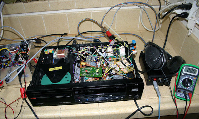
P.S. I have successfully powered a similar Philips CD player, using an external PSU box. And that PSU box had five separate toroidal transformers. It's shown below:

Here's the schema for the Philips CD players' PSU:
An externally hosted image should be here but it was not working when we last tested it.
The independent PSU is based on a common toroidal transformer + diode bridge + LM317.
What's the trick in grounding?
P.S. I have successfully powered a similar Philips CD player, using an external PSU box. And that PSU box had five separate toroidal transformers. It's shown below:
Last edited:
Just a bit further clarification ...
The schema below shows the Rudolf I/V stage I'm using.
When powered by an external PSU ... no problem until I/V ground is connected to CD player's PCB ground plane.
The schema below shows the Rudolf I/V stage I'm using.
When powered by an external PSU ... no problem until I/V ground is connected to CD player's PCB ground plane.
An externally hosted image should be here but it was not working when we last tested it.
Just a random thought...
The static DC voltage present on the I-DAC line will greatly influence the biasing of the discrete stage which by inference means that stage must have been designed to work under very specific operating conditions which presumably this player doesn't meet.
That would be my first guess.
The static DC voltage present on the I-DAC line will greatly influence the biasing of the discrete stage which by inference means that stage must have been designed to work under very specific operating conditions which presumably this player doesn't meet.
That would be my first guess.
Not sure??Just a random thought...
The static DC voltage present on the I-DAC line will greatly influence the biasing of the discrete stage which by inference means that stage must have been designed to work under very specific operating conditions which presumably this player doesn't meet.
That would be my first guess.
----> Using the external PSU, if I power the Rudolf I/V without any leads connected, all the biasing LEDs will glow bright (as normal).
----> Using the external PSU, if I power the Rudolf I/V with leads connected (except CD player's ground plane), all the biasing LEDs will glow bright (as normal).
I should've noted this earlier: If the Rudolf I/V stage is powered by the CD player's internal PSU rail (+15v), no problem! You can look at the Philips schema in my first post to see its topology.
Below image shows the I/V looking/behaving as normal (with good sound), powered by the CD player's internal +15v rail:
An externally hosted image should be here but it was not working when we last tested it.
Last edited:
Sounds a bit odd.
So if it all works when coupled up to the players own supply I would try:
1/ Confirm it works as above.
2/ Connect the 0V line of the external PSU to the ground of the appropriate regulator feeding the above circuit.
DO NOT alter the 15 volt supply at this stage, just confirm the player still works normally when player and external supply are active.
3/ Assuming it does, now transfer the 15 volt feed from the player to the external supply.
It should still work.
Always worth making sure that ground really is ground (meaning the same points) and also that the external supply isn't adding a 'ground' that is in some way at a different potential to those in the player. Ideally there should be no path via mains ground between the player and the PSU and any external equipment.
Just seen Chris's reply... something like that was my first thought and yet you say it works when using the internal supply.
Haven't been thru your steps.Just seen Chris's reply... something like that was my first thought and yet you say it works when using the internal supply.
I should've noted this also:
With CD player turned off, but with externally-powered I/V powered up (i.e., it's ON), as soon as I connect I/V ground to CD player ground, the biasing LEDs flicker and dim.
The external PSU is completely isolated from the CD player mains. It just supplies +15v.
It's pulling the emitter of q4 below the Vf of the LEDs.Haven't been thru your steps.
I should've noted this also:
With CD player turned off, but with externally-powered I/V powered up (i.e., it's ON), as soon as I connect I/V ground to CD player ground, the biasing LEDs flicker and dim.
The external PSU is completely isolated from the CD player mains. It just supplies +15v.
what does the output of the DAC look like, in terms of equivalent discrete components? what voltage does it want to run at?
When there is no power, the DAC output could be clamped between its rails?
Got it ... duh, me.
To get the I/V to bias properly, both the external PSU and CD player have to be on.
If the DAC is not sending current, the I/V won't bias properly (hence the dim biasing LEDs).
Because of a prev. SNAFU with external PSU powering, I was too safety conscious to turn all on simultaneously!
I think you guys suggested bias (Chris ??), so I'll give you credit")
To get the I/V to bias properly, both the external PSU and CD player have to be on.
If the DAC is not sending current, the I/V won't bias properly (hence the dim biasing LEDs).
Because of a prev. SNAFU with external PSU powering, I was too safety conscious to turn all on simultaneously!
I think you guys suggested bias (Chris ??), so I'll give you credit
Last edited:
- Status
- This old topic is closed. If you want to reopen this topic, contact a moderator using the "Report Post" button.
- Home
- Amplifiers
- Power Supplies
- Using multiple transformers in a CD player