I've played around with a lot of tube and SS based high voltage supplies, however both have their inherent drawbacks. SS is inherently harder to work with because of insulation issues for the pass devices and limited Safe operating area for any semiconductor. Furthermore a lot of work goes into making a solid state supply short circuit proof, whilst tubes will ignore most slip-ups.
For the one that looks hard enough, there are hundreds of examples of all tube regulated power supplies, some better engineered then others. They come in roughly two flavours, single pentode error amplifiers and double triode LTP. The single pentode has the advantage of being relatively simple. However in most cases the load regulation is pretty bad, and the open loop gain limited.
The LTP (either folowed by another LTP stage, or an pentode VAS, adds complexity to the circuit, and decreases the circuit performance.
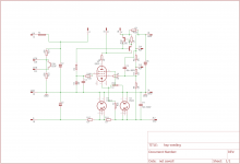
I have experimented with using a current source as load for a single pentode error amplifier, in an attempt to increase the gain and hence performance of a single pentode error amplifier. This circuit gave better performance than any variation other of a tube regulated that I've built.
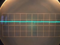
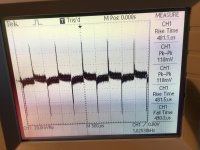
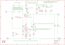
See the attached schematic for the first version of a CCS loaded pentode error amplifier i've tried. The two photo's is the AC coupled output voltage, whilst switching a 50mA load resistor on and off at a frequency of 1Khz. (Vout =250V Vin = 310V. The pass tube is a EL34 in triode)
Another Forum member noted that the used CCS impedance drops off sharply with an increase in frequency, i was thinking of using a cascode to increase the high frequency impedance of the CCS. This brings me to my next circuit, A EF184 based error amplifier that is fed from a cascode CCS. Taking an estimated impedance of 5 Meg from DC to 50Khz, the open loop gain (For the error amplifier alone) should be in the order of 5000-6000. (Ri= 400K S=15mA/V) I've used the approximation:
AV=Mu *(RL/(RL+RI)) So as far as i understand the Lower Ri of these high frequency pentodes is means that it is much easier to get close to their Mu as open loop gain in comparison to high Ri pentodes such as the 6AU6. If we take as a working assumption that high Mu low Ri tubes give the highest open loop gain, the EF184 comes out ahead by a wide margin. Followed by tubes such as the EF80 E83F.
Any thoughts?
For the one that looks hard enough, there are hundreds of examples of all tube regulated power supplies, some better engineered then others. They come in roughly two flavours, single pentode error amplifiers and double triode LTP. The single pentode has the advantage of being relatively simple. However in most cases the load regulation is pretty bad, and the open loop gain limited.
The LTP (either folowed by another LTP stage, or an pentode VAS, adds complexity to the circuit, and decreases the circuit performance.
I have experimented with using a current source as load for a single pentode error amplifier, in an attempt to increase the gain and hence performance of a single pentode error amplifier. This circuit gave better performance than any variation other of a tube regulated that I've built.
See the attached schematic for the first version of a CCS loaded pentode error amplifier i've tried. The two photo's is the AC coupled output voltage, whilst switching a 50mA load resistor on and off at a frequency of 1Khz. (Vout =250V Vin = 310V. The pass tube is a EL34 in triode)
Another Forum member noted that the used CCS impedance drops off sharply with an increase in frequency, i was thinking of using a cascode to increase the high frequency impedance of the CCS. This brings me to my next circuit, A EF184 based error amplifier that is fed from a cascode CCS. Taking an estimated impedance of 5 Meg from DC to 50Khz, the open loop gain (For the error amplifier alone) should be in the order of 5000-6000. (Ri= 400K S=15mA/V) I've used the approximation:
AV=Mu *(RL/(RL+RI)) So as far as i understand the Lower Ri of these high frequency pentodes is means that it is much easier to get close to their Mu as open loop gain in comparison to high Ri pentodes such as the 6AU6. If we take as a working assumption that high Mu low Ri tubes give the highest open loop gain, the EF184 comes out ahead by a wide margin. Followed by tubes such as the EF80 E83F.
Any thoughts?
Attachments
A quick update,
I have designed and built a circuit with a Cascode current source for the EF184, The neon voltage stabilizer has been put in the cathode lead of the error amplifier, because the EF184 has a maximum heater to cathode voltage of +-250V this allows running the EF184 and pass tube from the same supply. If the supply is tied to the output like in the schematic, this gives 300V as a sensible output voltage. The EF184 is made to operate at these levels of cathode to heater voltages.
Instead of the MJE350 I've opted for the 2SA1837. If we derate for chip heating, it will allow roughly 150V @10mA. So bigger triodes as pass tubes that require more negative voltage is a possibility.
The 6,3Vac heater is tied to the output of the supply, and single wave rectified to give +5V for the BC557 current source to operate.
Attachments

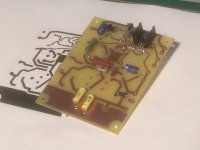
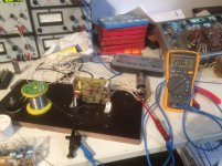
I've breadboarded and tested the circuit, it seems to work quite well, voltage fluctuations on the output @ 200V output whilst varying the input between 230-330V seem to be less then 100mV
I have yet to find time to cobble together a transformer+ rectifier so i can measure the ripple attentuation of the circuit. Also Load testing hasnt been performed yet.
I have yet to find time to cobble together a transformer+ rectifier so i can measure the ripple attentuation of the circuit. Also Load testing hasnt been performed yet.
Attachments
Unfortunately not, i shelved the project for now in favour of a fully solid state controlled supply. Feel free to experiment/use the circuit, you can substitute the MJE350 for the 2SA1837 the latter was marginally better as a cascode CCS, particularly the high frequency impedance. As far as higher voltage PNP devices its almost always the only choice available.
If you want i can send you the PCB plot and schematic.
The point behind this supply was getting good performance out of a single control stage.
I was thinking about using a transistor /pass tube cascade controlled by a transistor long tailed pair. There is a nice write up on this in an article published by Philips. PM if you want a copy.
Last edited:
- Status
- This old topic is closed. If you want to reopen this topic, contact a moderator using the "Report Post" button.