Hi All,
I plan to build a cheap dual variable +/-50V power supply with the following elements:
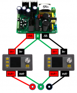
- 500W amplifier switching (+/-55)
500W amplifier switching power supply board dual-voltage PSU +/-55V (FR) | eBay
- 2x DPS5005 DC 50V 5A
DPS5005 DC 50V 5A LCD Digital Programmable Step-down Power Supply Module TE682 | eBay
Edit: DO NOT TRY THIS!!! THE SMPS WILL EXPLODE. YOU HAVE BEEN WARNED!!!
Planned connection is shown below.
I don't have the schematics of the DPS5005.
I am concerned about the common 0V connection at the PSU output: will it work?
Thanks for your help.
Jacques
I plan to build a cheap dual variable +/-50V power supply with the following elements:
- 500W amplifier switching (+/-55)
500W amplifier switching power supply board dual-voltage PSU +/-55V (FR) | eBay
- 2x DPS5005 DC 50V 5A
DPS5005 DC 50V 5A LCD Digital Programmable Step-down Power Supply Module TE682 | eBay
Edit: DO NOT TRY THIS!!! THE SMPS WILL EXPLODE. YOU HAVE BEEN WARNED!!!
Planned connection is shown below.
I don't have the schematics of the DPS5005.
I am concerned about the common 0V connection at the PSU output: will it work?
Thanks for your help.
Jacques
Attachments
Last edited:
Relook at your connections, you have in and out confused.
In/out connections are correct according to the datasheet.
Just tested them separately.
Last edited:
Why wouldn't it?I am concerned about the common 0V connection at the PSU output: will it work?
Why wouldn't it?
Because I have no idea of the ground connection inside the DPS5005.

scottjoplin is right.
To use your nice adjustable PSU's as +/- you need to feed them with isolated supplies.
So probably a separate supply for each side.
Also, running one switchmode converter from another can give some odd effects.
If the primary converter is not several times more powerful than those loading it, strange things may happen at start-up or during load transients.
I think a bench supply for testing needs to be particularly trustworthy or you may damage what you are testing or drive yourself mad with strange results.
Personally, I've bought a few junk ampliers to raid for things like transformers, caps etc.
What ground connection? Power in and power out is all I can see.
Edit: Oh, you mean the 0V is common in and out of the regulator?
Sorry, you are right, it won't work because of the common 0V at the power supply
I don't see a problem. The step downs are fully separated, I see no common connection between them.
Jan
As it seems to be a non-isolated buck converter, In- and Out- will be connected togetther in the module.I don't see a problem. The step downs are fully separated, I see no common connection between them.
Jan
The -ve regulator has its +in and +out connected to 0V. (by the internal connection on the _ve regulator if nothing else.)
So the -ve regulator won't work
The ebay pictures seem to show a fat toroidal inductor, suggesting it is indeed a simple buck regulator.
I don't see a problem. The step downs are fully separated, I see no common connection between them.
Not sure if the test is relevant but I checked all 4 pins of DPS5005 and found >1 MOhm for all in/in and in/out combinations.
I don't see a problem. The step downs are fully separated, I see no common connection between them.
Jan
Easy to check with a multi meter.
Yes that sounds pretty relevant.Not sure if the test is relevant but I checked all 4 pins of DPS5005 and found >1 MOhm for all in/in and in/out combinations.
It would suggest my posts have been based on an incorrect assumption and also that they've been seriously underselling their product.
Or there is a switch/fet/relay that disconnects when the unit is not running.
Or maybe a diode in the -Ve out line?
I have on my desk a 12A buck converter where the current limit is sensed in the out- line, could be a trap for the unwary who expect 0V to be 0V.
Sorry to hear that.I tested the circuit I have drawn.
Kaboom! The SMPS died in flames.
Do not attempt this. See post#1.
In hindsight, anything like this we should initially try in stages.
Get it running into some big resistors first, then add the regulators with some R in series.
Most SMPS are pretty tough these days, I recent bought some ebay 100W ones which cope nicely with short circuits and everything.
Applying volts to an output is often something they are not protected against though.
- Status
- This old topic is closed. If you want to reopen this topic, contact a moderator using the "Report Post" button.
- Home
- Amplifiers
- Power Supplies
- Cheap Dual Variable Power Supply ?