That's correct, although I think it's more in line with regulations for the fuse to be at the earliest point of connection as AC enters your chassis/device, but the usual design of a mains filter is such that it demands to be the earliest connection point, and practicality forces you to connect the fuse afterwards. Just try to keep your fuse close to the mains filter.So I guess it should be EMI Power Inlet -> Fuse -> Switch -> Transformer, correct?
There seems to be little consensus on the subject of mains filters. The subject pops up at semi regular intervals on this forum - in fact there's a thread at the moment titled "Large capacitor across mains: any sonic advantage for line conditioning?"
My own reference reading on this subject is a post by Bruno Putzeys from 2004 -
http://www.diyaudio.com/forums/class-d/38199-ucd180-questions-35.html#post466003
His take-home message is that if you are adding a mains filter at individual devices, as opposed to adding a filter at a shared power outlet, you should use "medical grade" or "B type" versions, which don't include a Y capacitor.
The Schaffner FN9222B is one such mains filter. Choose a low current rated filter - 1 amp is enough for a line level device - because apparently the design of these devices is such that at higher current ratings, the filtering is less effective.
I haven't read the article yet, but will, and probably follow your suggestion ")
Meanwhile, there is something I don't quite understand in the GlassWare LV-Regulator manual: They mention that if one uses a power transformer with a center-tapped secondary, then one should "attach the transformer secondary center- tap to bottom solder eyelet for rectifier D3".
The Triad transformer I want to use is marked "center tapped" on that web page, but I don't understand which pin of the secondary windings I would connect as GlassWare describes it?
If I am not mistaken, then that would not work with the Triad transformer, so I would just wire the secondaries in parallel and connect to AC in + and -.
Based on your earlier comment you have chosen the VPP16-1900 transformer model. If that is true, you have 2X8 Volt secondaries to work with for a total of 16VAC when connected in series.
You can parallel the 2X8VAC windings for 8VAC out and full current, but you must connect them correctly. Pin 12 to Pin 9 and Pin 10 to Pin 7. Pin 7 and Pin 10 are the ones with the dots in the documentation for the transformer. There is no center tap here. Therefore when you connect to the LV Regulator board you must use the Full Wave Bridge option which provides 8VAC.
If you want to use the center tap option you use the Full Wave Centre Tap option with the Centre Tap on the board. To get/make the Centre Tap on your transformer you must strap Pins 9 and 10 together to create your center tap so you have 3 wires total Pins 12, Pin 7, and Pins10 and 9 strapped as the centre tap to connect to the board.
Follow the instructions in the assembly manual from Glassware for initializing and testing your build.
I would use the more conventional full-wave-bridge rectifier mode, with the Triad wired for 2x 8VAC outputs in parallel, following ktham's explanation of connections - pins 12 and 9 tied, pins 10 and 7 tied. Now in this case, fully populate the GlassWare board, including D1,D3,C1 and C3.
OK, that's what I thought, so I guess I understood.Based on your earlier comment you have chosen the VPP16-1900 transformer model. If that is true, you have 2X8 Volt secondaries to work with for a total of 16VAC when connected in series.
You can parallel the 2X8VAC windings for 8VAC out and full current, but you must connect them correctly. Pin 12 to Pin 9 and Pin 10 to Pin 7. Pin 7 and Pin 10 are the ones with the dots in the documentation for the transformer. There is no center tap here. Therefore when you connect to the LV Regulator board you must use the Full Wave Bridge option which provides 8VAC.
... but now I am confused, didn't you just say I must use the Full Wave Bridge option?If you want to use the center tap option you use the Full Wave Centre Tap option with the Centre Tap on the board. To get/make the Centre Tap on your transformer you must strap Pins 9 and 10 together to create your center tap so you have 3 wires total Pins 12, Pin 7, and Pins10 and 9 strapped as the centre tap to connect to the board.
Follow the instructions in the assembly manual from Glassware for initializing and testing your build.
Yes, I think that is what I will do. I have a nice digital thermometer with probes which I can use to monitor the PSU temperature.I would use the more conventional full-wave-bridge rectifier mode, with the Triad wired for 2x 8VAC outputs in parallel, following ktham's explanation of connections - pins 12 and 9 tied, pins 10 and 7 tied. Now in this case, fully populate the GlassWare board, including D1,D3,C1 and C3.
Second thoughts on Allo DigiOne
Yesterday I was checking out some alternatives to the Allo DigiOne. I just find the $99 a bit high... at least in comparison to other HATs that provide similar features.
I stumbled upon the 502dac from Pi 2 Design. It appears to have pretty much the same features as the Allo DigiOne, but also includes a DAC and a few more output options, at $89. This would make more sense for me if I would want to ever use the streamer in a system where no DAC is available (like in my office). The 502dac had a few pretty good reviews as well... any thoughts on that would be appreciated.
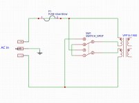
PSU PCB Layout
Further I started to figure out how to design the PCB for the transformer. I want to include a fuse and a 115/230 switch on it. I found the following, which I think will work:
Littlefuse Fuse Holder
C&K Voltage Selector
I would like to use EasyEDA or something similar to get the PCB made. The problem is, I cannot find the transformer in their database... so I don't really know how to design the schematic and convert it to a PCB layout???
Attached is the schematic I have so far. Please bear in mind, this is the first schematic I ever created...
Attachments
To be clear, you can use either full-wave-bridge mode, OR full-wave-centre-tap mode, but each requires a different wiring configuration of your transformer outputs. I suggest full-wave-bridge mode.
Yes, that 502DAC looks respectable, but it's likely to be a step down in overall SQ from the rPi - the Allo DACs are expensive for a reason - they're part of the rare class of rPi hat-DACs which have good quality onboard audio clocks, and feed this master clock (in the form of word sync) back into the rPi as playback reference. And we have already established that you have an external DAC which is likely to be worthy of this class of transport.
An alternative approach would be to buy a second (el cheapo) external spdif DAC, just for your office. Here's one for $40 + $12 shipping -
HiFi AK4118+AK4490+XMOS decoder Coaxial Optical USB DAC 192K 24BIT | eBay
Hell, why not buy a second Raspberry Pi - apparently they're just $35 in the US, and have a completely separate second playback system.
Add an el-cheapo hat-DAC for about $20. Or there's even a small PCM5102 hat-DAC on eBay for $5!
Then again, the highly regarded ALLO Boss DAC is just $59. rPi + BOSS = $94 total. Modest money for a good quality audio renderer.
It's true, for the price, I could just set up another rPi.To be clear, you can use either full-wave-bridge mode, OR full-wave-centre-tap mode, but each requires a different wiring configuration of your transformer outputs. I suggest full-wave-bridge mode.
Yes, that 502DAC looks respectable, but it's likely to be a step down in overall SQ from the rPi - the Allo DACs are expensive for a reason - they're part of the rare class of rPi hat-DACs which have good quality onboard audio clocks, and feed this master clock (in the form of word sync) back into the rPi as playback reference. And we have already established that you have an external DAC which is likely to be worthy of this class of transport.
An alternative approach would be to buy a second (el cheapo) external spdif DAC, just for your office. Here's one for $40 + $12 shipping -
HiFi AK4118+AK4490+XMOS decoder Coaxial Optical USB DAC 192K 24BIT | eBay
Hell, why not buy a second Raspberry Pi - apparently they're just $35 in the US, and have a completely separate second playback system.
Add an el-cheapo hat-DAC for about $20. Or there's even a small PCM5102 hat-DAC on eBay for $5!
Then again, the highly regarded ALLO Boss DAC is just $59. rPi + BOSS = $94 total. Modest money for a good quality audio renderer.
Whether the Allo DigiOne sounds better than the 502Dac I wouldn't know until I would A/B test the two... I don't know. I would like to know in detail what makes the Allo DigiOne worth its price. Looking at this comparison table, it also shows noise clocks for example.
I setup my Raspberry today with RuneAudio; 'had a bit of trouble to setup the static IP (I don't have nor want DHCP), but now it's running smoothly, and functionality is definitely very good. First tests completed successfully
I still need to figure out how to design the PCB board for the transformer though; any suggestions for a good EDA program? I tried a couple, but didn't get very far yet. Since I am on Linux, I will probably try out KiCad EDA, hopefully I will end up with some proper gerber files so that I can get a board for this.
I still need to figure out how to design the PCB board for the transformer though; any suggestions for a good EDA program? I tried a couple, but didn't get very far yet. Since I am on Linux, I will probably try out KiCad EDA, hopefully I will end up with some proper gerber files so that I can get a board for this.
I'm playing with Fritzing Fritzing
I earlier made an assumption that the Pi2Design 502DAC does not operate in master mode, sending the derived bit clock and word clock back to the rPi ... but I see now that it DOES. So it's on the same technical level as ALLO and Hifiberry DACs, and may be considered a serious competitor to the ALLO BOSS, with the additional benefit of having a s/pdif transmitter.
But is it as serious a competitor to the ALLO DigiOne?
the 502DAC appears to employ the conventional form of s/pdif isolation using a small transformer (it's located behind the BNC connector)
but the DigiOne has a full I2S isolation circuit, and this probably explains why the DigiOne is noticeably dearer than the other hats on that comparison list.
How the added technical sophistication of the DigiOne translates to audible differences will probably only be known by listening comparisons.
But is it as serious a competitor to the ALLO DigiOne?
You may notice on the Pi2Design comparison list that the 502DAC and DigiOne are both listed as having "Isolated Digital Output" ... but they are quite different in this regard;I would like to know in detail what makes the Allo DigiOne worth its price.
the 502DAC appears to employ the conventional form of s/pdif isolation using a small transformer (it's located behind the BNC connector)
but the DigiOne has a full I2S isolation circuit, and this probably explains why the DigiOne is noticeably dearer than the other hats on that comparison list.
How the added technical sophistication of the DigiOne translates to audible differences will probably only be known by listening comparisons.
I heard about Fritzing, it looks good. Works on Linux too, will check it out. Thanks!I'm playing with Fritzing Fritzing
Thanks for the explanation. I had the feeling the 502DAC must be pretty good. I will think about it, maybe I will get the Allo DigiOne as well and compare them one day...I earlier made an assumption that the Pi2Design 502DAC does not operate in master mode, sending the derived bit clock and word clock back to the rPi ... but I see now that it DOES. So it's on the same technical level as ALLO and Hifiberry DACs, and may be considered a serious competitor to the ALLO BOSS, with the additional benefit of having a s/pdif transmitter.
But is it as serious a competitor to the ALLO DigiOne?
You may notice on the Pi2Design comparison list that the 502DAC and DigiOne are both listed as having "Isolated Digital Output" ... but they are quite different in this regard;
the 502DAC appears to employ the conventional form of s/pdif isolation using a small transformer (it's located behind the BNC connector)
but the DigiOne has a full I2S isolation circuit, and this probably explains why the DigiOne is noticeably dearer than the other hats on that comparison list.
How the added technical sophistication of the DigiOne translates to audible differences will probably only be known by listening comparisons.
A bit of an update on this project, I hope someone is still following this thread... some questions at the end of this post.
Raspberry Pi 3 is here and running fine (with a 5V, 2.5A SMPS). I tried Volumio first, but it refused to index my music library (as in zero indexed files). Switched to RuneAudio, and everything worked great. It was just a bit of a hustle to change from DHCP to static IP, but that is working fine now too.
Sound is quite good, only with some 24/192 files I had a few strange "sizzling" noises (using the USB output of the pi).
After a bit of thinking and reading here and there, I decided I will go with a DAC HAT instead of a "Digi HAT". Probably the Allo Boss. It's just that I want that bit of independence, and I am also not 100% sure if I will keep the RME ADI-2 Pro. It's a great DAC, just that I am so used to vintage amps/preamps with big buttons and knobs and dials, that I find the usability a bit cumbersome with the tiny buttons, many menus etc.
I am still waiting for the GlassWare kit.
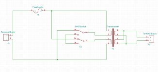
Meanwhile I went step-by-step through the tutorials of KiCad, a EDA software that was recommended by some on this forum. It took a while to get the footprints etc. right, since none of my chosen components were in the library. A great piece of software, this was fun.
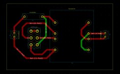
I have completed the schematic and the PCB layout now, and am just very curious of how bad (or good?) my first PCB layout is.
Attached screenshots of schematic and layout. This is basically a PCB for an AC to AC circuit, with a fuse, a voltage switch (115/230), a transformer and a screw terminal at each end. Missing are the mounting holes and some informative silk screen text...
Trace width is 2mm, which I understand is a good idea for higher voltages(?).
What I don't really understand is, whether I need to worry about ground planes. As far as I understand, this is important for low level circuits, but not for this circuit, which is really all AC. Could someone shed some light on this for me?
Raspberry Pi 3 is here and running fine (with a 5V, 2.5A SMPS). I tried Volumio first, but it refused to index my music library (as in zero indexed files). Switched to RuneAudio, and everything worked great. It was just a bit of a hustle to change from DHCP to static IP, but that is working fine now too.
Sound is quite good, only with some 24/192 files I had a few strange "sizzling" noises (using the USB output of the pi).
After a bit of thinking and reading here and there, I decided I will go with a DAC HAT instead of a "Digi HAT". Probably the Allo Boss. It's just that I want that bit of independence, and I am also not 100% sure if I will keep the RME ADI-2 Pro. It's a great DAC, just that I am so used to vintage amps/preamps with big buttons and knobs and dials, that I find the usability a bit cumbersome with the tiny buttons, many menus etc.
I am still waiting for the GlassWare kit.
Meanwhile I went step-by-step through the tutorials of KiCad, a EDA software that was recommended by some on this forum. It took a while to get the footprints etc. right, since none of my chosen components were in the library. A great piece of software, this was fun.
I have completed the schematic and the PCB layout now, and am just very curious of how bad (or good?) my first PCB layout is.
Attached screenshots of schematic and layout. This is basically a PCB for an AC to AC circuit, with a fuse, a voltage switch (115/230), a transformer and a screw terminal at each end. Missing are the mounting holes and some informative silk screen text...
Trace width is 2mm, which I understand is a good idea for higher voltages(?).
What I don't really understand is, whether I need to worry about ground planes. As far as I understand, this is important for low level circuits, but not for this circuit, which is really all AC. Could someone shed some light on this for me?
Attachments
Looks good to me, with one reservation - I prefer to see the mains fuse as close as possible to the point of entry into the enclosure. So if the input side of your transformer board is mounted very close to the chassis AC entry point, that's acceptable, but if the cable length is to be anything more than a few centimetres then I think the mains fuse should not be on the board at all, but mounted to an appropriate point on the chassis.
You could, and possibly should, also add a 2nd fuse between the transformer secondary and regulator - 4A would be good. I see that the GlassWare LV-Regulator does not include a fuse at its input, so you should probably add such a fuse at the output side of your transformer board.
You could, and possibly should, also add a 2nd fuse between the transformer secondary and regulator - 4A would be good. I see that the GlassWare LV-Regulator does not include a fuse at its input, so you should probably add such a fuse at the output side of your transformer board.
The board will be right behind the IEC inlet, my intention is to put it as close as possible.Looks good to me, with one reservation - I prefer to see the mains fuse as close as possible to the point of entry into the enclosure. So if the input side of your transformer board is mounted very close to the chassis AC entry point, that's acceptable, but if the cable length is to be anything more than a few centimetres then I think the mains fuse should not be on the board at all, but mounted to an appropriate point on the chassis.
You could, and possibly should, also add a 2nd fuse between the transformer secondary and regulator - 4A would be good. I see that the GlassWare LV-Regulator does not include a fuse at its input, so you should probably add such a fuse at the output side of your transformer board.
Putting a fuse on the output side is a good idea. So that would go where the "+" is, right? Just confirming. Is there really a + and - in an AC circuit?! It's confusing me a bit...
By the way, the PCB layout is wrong... it's not quite obvious, but in KiCad the traces on the front layer are red, on the bottom green. I have all my traces on the front side of the board, where the components are mounted. As far as I know, with through-hole components, the majority of traces should be on the bottom. I studied a old (1998 or so) 2-layer amplifier board a bit... that's how it was done there, too.).
It also occurred to me, that I should really have all the parts ready before ordering the PCB... so that I can print out the board and place the components onto it, to see if everything fits. Oh well, it's my first time... a lot to learn...
Still need to mark the mounting holes and find some stand-offs, otherwise I think I got all the parts figured out.
Your incoming mains AC needs to be fused on the active line, which I see on your schematic is marked as "+".
This fuse is for safety ie. not electrocuting yourself, and not burning down your house.
At the transformer secondaries you can connect a fuse to either of the 2 output connections.
This fuse is to protect the equipment which your transformer connects to ie. it's easier to replace a fuse than to replace a fried regulator, or worse, downstream.
Yes, of course, makes sense... on the mains side there is an active and a neutral line, and earth which will go to the chassis.
Now just waiting for the parts to come in.
Meanwhile I am looking at the arrangement of the AC board, regulator, and raspberry/DAC. Case inside dimensions are about 17 x 13 inches, lots of space. I am thinking about putting the AC board and regulator all the way to the left, and the raspberry/DAC sort of in the middle...
I don't know what's more important to keep short, the 5V power cable, or the RCA cable (I will wire the DAC's RCA outputs to a pair of panel-mount RCA jacks)?
Generally you want to keep DC power supply cables (or PCB traces) as short as possible, though this is more important at the final regulation stage, rather than pre-regulation stage - such as your 5V supply to the rPi.
The theory of this is a bit over my head (I think ripple is the problem) but if you want to know more you may want to ask others on this forum for an explanation.
Don't be too concerned about the length of audio cables, certainly not within a standard size chassis. Just follow good practice: twist the audio cable pairs, and keep them away from AC cables, and keep them away from your regulator.
Generally you want to keep DC power supply cables (or PCB traces) as short as possible, though this is more important at the final regulation stage, rather than pre-regulation stage - such as your 5V supply to the rPi.
The theory of this is a bit over my head (I think ripple is the problem) but if you want to know more you may want to ask others on this forum for an explanation.
That's what I thought... At first I had the idea of using a ribbon cable to separate the DAC HAT and Raspberry, which would make connections easier (I don't particularly like the mini-USB power plug right under the RCA connector), but I figured that is a bad idea. The connection between the two should be as short as possible, e.g. just plug the HAT onto the Raspberry, no ribbon break-out cables...
I read about twisting the cables, and I believe I should I do that for the power supply cable too?Don't be too concerned about the length of audio cables, certainly not within a standard size chassis. Just follow good practice: twist the audio cable pairs, and keep them away from AC cables, and keep them away from your regulator.
For the RCA cable, I actually thought about using a COAX. I have a few feet of that nice Canare coax 75Ohm cable left. Someone has done this before... not sure if it's a good idea, improves things or the opposite...
Yes, twist all cables - AC power, DC power, audio.
Sure, I seem to recall that coax was popular at one stage for analogue interconnects. Be aware that any potential benefit of this cable may be due to it having a solid core, rather than its construction-type, so if you were to use a particularly flexible version of coax, that would likely contain finely stranded core, and have no benefit at all over other cable types.
And be aware that the rigid nature of coax can make it awkward to deal with, and it can be fiddly to strip and solder.
A good source of solid core wire is cat5 ethernet cable - cut and peel away the outer jacket, then separate the inner pairs, and give them some additional twists.
Or Mogami W2944 console cable is well regarded for internal wiring.
Or at the extreme end of the scale cotton insulated silver wire is claimed to be the best!
Here are some thoughts for your design consideration.
The Allo Boss has power pins to allow you to separately power it from the RPi. This will require another 5V regulator board should you choose to examine/test this configuration. Accordingly you will then have to re-lay your PCB for separate secondary windings instead of paralleling them to get two 8VAC outputs for your regulator. Lay it out so that the windings can be paralleled by a jumper on the board.
You can hard wire/solder power leads to the Rpi and the Allo Boss instead of using connectors/plugs. Use 22 or 24 ga wire.
I have some audio cable, 2 conductor shielded, 3.5mm black which I can send you for your build. It is new on a roll and I can take off 10ft. and send it to you. Send me a PM with your address.
The picture is of my RPi /HAT/DAC test platform where I have an Allo Piano 2.1 DAC with Reclocker, a ESS DAC with Kali Reclocker, and a Dial DAC all with their individual Glassware power supplies in a re purposed desktop PC case. I do not have any interference or cross talk between the units even with the different power wiring schemes.
Attachments

I agree with ktham; your project is currently so extensive that it would be a shame not to go just a bit further and accommodate a second 5V supply for the DAC-hat.
The DAC-hat deserves a high quality, low noise, such as the LT3042, ADM7150, or TPS7A4700 ...
but I see the BOSS DAC's onboard regulators are LT3042 - OK, in that case I would exclude LT3042 from your choice of pre-regulators, because by combining two different regulator types your get to reduce two different noise bandwidths.
ADM7150 and TPS7A4700 regulator kits can be found at diyinhk. You could also try eBay and AliExpress, with some price versus quality considerations.
Regarding the transformer, sure, you could split your Triad's secondaries to supply two regulators, but it seems to me that you have plenty of space in your enclosure, so I would use a second (smaller) transformer for the DAC-hat. Something like this Hammond -
229A16 - Hammond Mfg.
8VAC 700mA 48x40x22mm
or if you're more comfortable with a higher current rating, the next size up is
229B16 - Hammond Mfg.
8VAC 1.4A 64x51x27mm
Last edited:
- Status
- This old topic is closed. If you want to reopen this topic, contact a moderator using the "Report Post" button.
- Home
- Amplifiers
- Power Supplies
- Linear PSU for Raspberry Pi 3, which one? Confused.