It is big deal at front stages where signals are extremely small, when SR ( signal to noise level ) is poor.What's the big deal about noise?
Of a paramount importance about signals from deeper space probes sending pictures from far away planets.
Mostly BS about well designed power amplifiers.
Sure.
What's the opinion on how much noise is too much for a MC amplifier psu? (you may have to make some qualification regarding PSRR)
And what is the effect on sound quality of too much psu noise?
And regarding the thread topic, how noisy is a smoothing cap compared to an LM317?
What's the opinion on how much noise is too much for a MC amplifier psu? (you may have to make some qualification regarding PSRR)
And what is the effect on sound quality of too much psu noise?
And regarding the thread topic, how noisy is a smoothing cap compared to an LM317?
Last edited:
And regarding the thread topic,...............
How refreshing!!
Well, in terms of ripple (which certainly is noise), every 10-fold increase in capacitance reduces ripple by 20db. An OnSemi LM317 reduces 120Hz ripple by 80 db. You'd have to use a MIGHTY big cap to equal the LM317.how noisy is a smoothing cap compared to an LM317?
I think you misunderstood. Traderbaum is talking about noise induced by caps on the output of the power supply.
Caps as any componant do make thermal noise.
This has been oversighted in most fancy super duper calculations giving extremly low noise figures.
All componants make thermal noise. So a calculated noise going below, doesn't make any sense.
Caps as any componant do make thermal noise.
This has been oversighted in most fancy super duper calculations giving extremly low noise figures.
All componants make thermal noise. So a calculated noise going below, doesn't make any sense.
I’m armchair brainstorming.
Eg: LM317 + 1mF vs LM317 + 1uF
uhh isn't that just moor capacitor?
RE Armchair quarterbacking >The play you are trying to call was tackled in the backfield.

How about just building it' and if it' doesn't suit your needs, upgrade / change the regulator part or roll your own. Folks seem to forget that a monolithic V regulator chip aka 3 terminal regulator, is the cheap-n-easy way of getting great ripple reduction without the BF'ing low-pass filter components. Adding them back on the output is pretty silly from my view, it doesn't make it doubly good. Understand that using a 3T linear regulator circuit is an engineering compromise for both noise and ripple, ideally the burden is distributed equally from a systems engineering perspective.
which can be interpreted as ..IF your fancy new audiophile' preamp requires exotic DC supplies, sumptin' aint right. Of course it might be a sales gimmick too. The earliest tube radios used all batteries, b/c most folks didn't have AC electricity. You are welcome to go back to the stone-ages. its a balance in life too The Audiophile Club of Athens on Vimeo see that fella at 02:20 LOL perfect electricity!
Last edited:
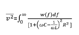
At 300K, a 100uF capacitor has the same thermal noise as a 2.5k resistor, about 6.4nV/RtHz...but
Just to keep things clear, only the real component of impedance of a capacitor, the actual DCR, creates Johnson (thermal) noise. The reactive component is noiseless. The same goes for inductance.
So, if the 100µF capacitor has a DCR of 2.5kΩ, then it will be as noisy as 2.5kΩ. It probably does not, and something like 10-100mΩ is more likely. That's the thermal noise contributor, not the impedance of the cap.
What I mean is that the regulator series impedance is shunted by the capacitor impedance so the larger the capacitor the lower its impedance and the less % contribution the regulator makes to the combined impedance.uhh isn't that just moor capacitor?
The regulator noise is proportionally reduced as it is divided across the impedances and the cap is relatively noiseless.
Therefore, noise reduction is a reason to use a large cap with a regulator.
I have no idea what this means and I don’t think I want to.RE Armchair quarterbacking >The play you are trying to call was tackled in the backfield.

Last edited:
Right.Just to keep things clear, only the real component of impedance of a capacitor, the actual DCR, creates Johnson (thermal) noise. The reactive component is noiseless. The same goes for inductance.
http://www.ti.com/product/OPA2350
I was curious to know what was inside my analyser. I was rather surprised by what I found. Ken Ishiwata has said the sound quality of the 1 bit Marantz machines was mostly dictated by the limitations of CMOS. I suspect if this chip is typical it should be very good.
That brings me to my question. Has anyone built an add on for an analyser with gain of 10 and 10 MHz useful range or in that region. I know from the start it would add noise and I would have to calculate approximately the real noise. My thoughts are to use a video op amp. However it might be better to use a descrete circuit. I would imagine BC327/337 might work at a pinch ( circa 0.6 nV ). Some of the video op amps might set difficult parameters. For the work I do a 10 K input impedance would be OK.
For now I will leave the OPA2350 alone.
OPA2350 is similar to TL082 up to 1 kHz and more like 741 up to 500 Hz. After 7kHz it meets it's general spec, distortion is good ( < - 115 dB up to 7 kHz - 100 dB 20 kHz G =1 2.5 Vpp). Not unlike many video op-amps I have seen. Output current is 40 mA in source and sink. Slew rate 22V/uS, unity gain stable, will tollerate a short circuit. Rail to rail 5V supply. Now I know it I would like better. It seems ideal to boost the gain if I can. Having said that it has always been able to tell me enough. I bought it as a stop gap and never found it incapable so it soldiers on.
Sounds like you want a spectrum analyser?http://www.ti.com/product/OPA2350
I was curious to know what was inside my analyser. I was rather surprised by what I found. Ken Ishiwata has said the sound quality of the 1 bit Marantz machines was mostly dictated by the limitations of CMOS. I suspect if this chip is typical it should be very good.
That brings me to my question. Has anyone built an add on for an analyser with gain of 10 and 10 MHz useful range or in that region. I know from the start it would add noise and I would have to calculate approximately the real noise. My thoughts are to use a video op amp. However it might be better to use a descrete circuit. I would imagine BC327/337 might work at a pinch ( circa 0.6 nV ). Some of the video op amps might set difficult parameters. For the work I do a 10 K input impedance would be OK.
For now I will leave the OPA2350 alone.
Or maybe just some narrow tuning filters?
No it's not quite that simple, but lets say it's OK for a 1st order approximation. Take the impedance of what ever capacitor you want and overlay it on a graph of the regulator's output impedance. Also noting the SRF of the capacitor is inversely proportional to the size (and lead spacing) of that part. As discussed the capacitor is a component not a filter, pasted directly on the output of another component or filter could have unintended consequences. Infact blindly doing so could spoil the data sheet performance of a simple series V regulator or change the stability of the preceding stage, for example a SMPS. Clearly a huge electro part wont compare down low and is becoming useless at mid to high band audio, right?.What I mean is that the regulator series impedance is shunted by the capacitor impedance so the larger the capacitor the lower its impedance and the less % contribution the regulator makes to the combined impedance.
The regulator noise is proportionally reduced as it is divided across the impedances and the cap is relatively noiseless.
Therefore, noise reduction is a reason to use a large cap with a regulator.
If the regulators ripple reduction and noise contribution added together using root sum of squares doesn't meet the goal, change the 3T regulator OR add more stages of regulation and / or low pass filtering. What is the goal? Isn't 200 uV RMS like from a good laboratory grade PS enough.
Last edited:
Just to keep things clear, only the real component of impedance of a capacitor, the actual DCR, creates Johnson (thermal) noise. The reactive component is noiseless. The same goes for inductance.
Attachments
Thanks, I had forgotten caps do not make Johnson noise.
What about other noise kinds ? I wonder about noise from the cap dielectric or some sort of granularity with current charging or discharging.
I have seen huge caps used on ultra low noise microphone preamps. Two caps at the input to DC isolate from phantom power. Huge caps because of overkill voltage. I never found the reason why, but I do know the designer knew what he was doing.
I guess this has to do with noise, any idea ?
About power supply noise, the preamps I am talking about are powered with LM317 117 for +16 -16 +48. There is absolutely nothing fancy, just what is recommended in datasheets.
It is indeed ultra low noise, at full gain 60dB, not any hiss, zilch, nothing.
Here we are talking about true, no bull, 4 preamps , a design for actual 1uV/sqrtHz noise density.
Just plain, op amps and regulator datasheet recommendations about power rails.

- Home
- Amplifiers
- Power Supplies
- LM317 load capacitance