+1Your "redraw" is misleading.
he's missing the main outputs. LOL
Contrarians often take examples out of context.
This is half wave rectification, so it has a tougher road to hoe.
Unbalanced current draw could raise ripple voltages. The negative Vreg. performance isn't equal to its brother.
Last edited:
No it isn'tThis is half wave rectification
No it isn't
It's a voltage doubler with a reference ground at the central tap. The ripple frequency is equal to the mains freq.
No . It's the regulator circuit how it was published by Elektor.he's missing the main outputs
The mentioned additional connections before the 10 ohm-resistors, which you call "main outputs", where used by me in an own, quite similar circuit, not in the shown elektor circuit.
the connections for a transformer are: AC1, G1 (center tap), AC2I imagined the transformer centre tap because I expected it to be there
Ah, thank you, all becomes clear now after infinia's attempt to confuse methe connections for a transformer are: AC1, G1 (center tap), AC2
")
The transformer doesn't appear anywhere on photos or schematics. I assumed its an outboard Xfmr so a 2 wire connector for LV AC is bog standard. It's a very common topology nothing wrong here.* Two separate winding with 2x fullwave bridges would be preferred for several reasons, but that's 4 wires. I assume theres another supply for relays and any digital controller displays. Feeding us incomplete bits / pieces and guessing games isn't helping anyone.
*try to find a wall wart or power brick with a 3 wire connector not as plentiful as a 2 wire. Many advantages to keeping mains potential away from the electronics esp. if its SELV safety extra low voltage.
*try to find a wall wart or power brick with a 3 wire connector not as plentiful as a 2 wire. Many advantages to keeping mains potential away from the electronics esp. if its SELV safety extra low voltage.
Last edited:
Well, it seems that the easiest and best solution is to put a 220uF cap on the adjustment leg and a several-hundred uF cap with ~ 100mΩ ESR on the output. Then I saw this on eBay:
AC-DC LM317 LM337 LF353 Servo Rectifier Filter Power Supply Module Adjustable | eBay
Cheap, and it uses the LF353 servo idea. Anyone try one of these? Opinions? I believe the caps would have to be changed.
AC-DC LM317 LM337 LF353 Servo Rectifier Filter Power Supply Module Adjustable | eBay
Cheap, and it uses the LF353 servo idea. Anyone try one of these? Opinions? I believe the caps would have to be changed.
It is a switching regulator. Normally optimized for power efficiency rather than low noise. Super cheap tho.Opinions?
Last edited:
Well, it seems that the easiest and best solution is to put a 220uF cap on the adjustment leg and a several-hundred uF cap with ~ 100mΩ ESR on the output. Then I saw this on eBay:
AC-DC LM317 LM337 LF353 Servo Rectifier Filter Power Supply Module Adjustable | eBay
Cheap, and it uses the LF353 servo idea. Anyone try one of these? Opinions? I believe the caps would have to be changed.
looking at the PCB I could never guess that was a switching smps.It is a switching regulator. Normally optimized for power efficiency rather than low noise. Super cheap tho.
Yet the description does say
Is it possible the translation from chinese has got this wrong?Note 1: This is buck regulator power supply board, Itself no booster effect. Such as AC 18V is rectified to get DC 25V, that it's the highest adjustable voltage is 25V.
Absolutely possible!Is it possible the translation from chinese has got this wrong?
I'm going by the description saying "buck" and the claim that it will turn 18Vac into 25Vdc, a ratio of 1.4. Although peak AC is 1.4 x RMS it wouldn't be able to output this peak level without a higher dc somewhere. And it uses a dual op-amp...
R
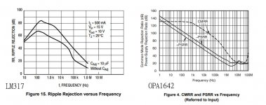
I should have met a wise man earlier. My application is simple, just op amp for tiny amp. Ripple is the least of my concern. Bcs op amp has very high PSRR to filter it again. But as frequency rise, performance decrease. CRC can handle it I guess. Another concern will be output impedance.
What about remote sensing, if I use LM317 337, then it'll be like 5 wires goes to the load? I've never try this trick before, need a wise man to share some experience.
A wise man once said "return the noise from whence it came". This includes mains IEC filters , and ferrite beads and MLCC at signal entry / exits. Use snubbers at the switches / diodes, Use common mode chokes for SMPS , Class D power, etc. 1st you have to master the measurements before you can determine a solution.
I should have met a wise man earlier. My application is simple, just op amp for tiny amp. Ripple is the least of my concern. Bcs op amp has very high PSRR to filter it again. But as frequency rise, performance decrease. CRC can handle it I guess. Another concern will be output impedance.
What about remote sensing, if I use LM317 337, then it'll be like 5 wires goes to the load? I've never try this trick before, need a wise man to share some experience.
Can't you put the LMs at the load ? The PS giving filtered unregulated ,Vin+ and Vin- to the LMs, which is only 3 wires and would not make stability issues as remote sensing could do.What about remote sensing, if I use LM317 337, then it'll be like 5 wires goes to the load? I've never try this trick before, need a wise man to share some experience.
Heed the datasheet advice for output capacitance and ESR.
I was working on project for myself and using a LDO regulator I found the choice of cap was important.
http://www.mouser.com/ds/2/348/baxxbc0-e-1018445.pdf
Page 9 shows the stable region in regard to capacitance and ESR.
I used these at the output with great results:
http://nichicon-us.com/english/products/pdfs/e-rns.pdf
With trace resistance it ended up right in the stable region.
What about remote sensing, if I use LM317 337, then it'll be like 5 wires goes to the load? I've never try this trick before, need a wise man to share some experience.
No, just three: connect the lower end of Vset resistor (the one between Vadj pin and 0v) to 0v at the load - this wire to include the Cadj noise current also, i.e. connect Cadj across Rset and take one wire to 0v at the load.
The resistor that sets the current , between Vout and Vadj pins, MUST remain as close as possible to the LM317 itself - the extended application note tells you this and explains why; as does the excellent tnt-audio article series already linked above.
HINT: the LM317 is a pretty good & useful 1.25v regulator; using it as an adjustable regulator is a hack, and decreases its performance in inverse proportion to the gain you add to it. You must keep the current-setting resistor (between vout and Vadj) very close to the body of the LM317 , because this is the only way to ensure an accurate 1.25v is maintained across it, without mixing-in the voltage noise product of (load -current x wiring-to-load resistance).
Last edited:
I should have met a wise man earlier. My application is simple, just op amp for tiny amp. Ripple is the least of my concern. Bcs op amp has very high PSRR to filter it again. But as frequency rise, performance decrease. CRC can handle it I guess. Another concern will be output impedance.
What are your concerns? PSRR due to limited negative feedback is common, luckily it still remains good where RLC filtering does not.
*For example A singled ended linear preamp for small class-D amps both being supplied by the same cheap SMPS can indeed be a handful. Common mode noise is usually the killer here. many time you can see it on a scope but its not a problem on reasonable designs. Class-D PA's have differential inputs, Do use them.
No don't do that, a wise man certainly wouldn't advise 3T remote sensing for milliwatt loads, certainly not on an adjustable one. Locate the linear regulator close to any critical loads to avoid noise or ripple pickup. Any additional PSRR can come from input or output RLC filters. Avoid L on dynamic loads.What about remote sensing, if I use LM317 337, then it'll be like 5 wires goes to the load? I've never try this trick before, need a wise man to share some experience.
Remember the negative and positive rails on op-amps have different PSRR as do LM337 from the 317.
Originally I was thinking main power harmonics and switching power of laptop will have effect on main power. when frequency is higher above 10khz, it will be more difficult for 3-T regulator and op amp to handle. but I read this thread carefully again, RCL filter will be a good fix.
According to Simple Voltage Regulators Part 2: Output Impedance
http://www.tnt-audio.com/gif/schem_lm317_layout.gif
The right circuit has a twin ground connection: the lower one carrying the return load current, and the upper one carrying (almost) no current, but connecting the LM317's adjust network to true load ground.
So I don't need to do that? Normally I just short LM317, LM337's Radj GND together, and connect it to star ground. With my new project, I use op amp + buffer. Load is extremely light, with opa1642, only Iq *2 (1.8mA)+ output current in uA range.
http://www.diyaudio.com/forums/attachments/chip-amps/640406d1508104694-project-cute-16w-cute16-jpg
Another silly question, load GND on opa amp is the input gnd, feedback gnd, output gnd, is that correct? So I shouldn't connect decouple capacitor gnd to LM317, LM337 0V.
Attachments
Fix it where you find it. Good practice measuring switching PS ripple and noise alone with a dummy load. Identify that there's three components of ripple, 1st is mains related, 2nd loop sampling related and lastly hash noise.Originally I was thinking main power harmonics and switching power of laptop will have effect on main power. when frequency is higher above 10khz, it will be more difficult for 3-T regulator and op amp to handle. but I read this thread carefully again, RCL filter will be a good fix.
You must filter them by different means. FWIW Laptop bricks come in many flavors / grades stick to name brands for less headaches.
No , that model is weirdly unreal. I'm not going down his rabbit hole. LoLSo I don't need to do that?.
Look at the PSRR and noise test circuits in the data sheet for clues. Use 3 smallish decoupling caps placed on every terminal. Build it close to the device, just like op-amp decoupling. Connect the input and output traces / wires at their respective caps and you'll be golden. If you have long interconnects or dynamic loads at the 3T Vreg you may have to add or modify the circuit. Like everything , There is no universal one design regulator device or circuit that solves every problem.
PS thanks for providing details on your audio application / circuit. it helps!
Last edited:
Hmmmm....I don't see it that way. The LM317, 337 and LF353 are all linear analog devices. I don't see any switching going on here at all. It appears to me to be a standard LM317/337 linear regulator with an added LF353 for feedback---presumably to reduce noise and maybe tighten regulation.It is a switching regulator. Normally optimized for power efficiency rather than low noise. Super cheap tho.
- Home
- Amplifiers
- Power Supplies
- LM317 load capacitance