On the diyaudio power supply boards sold here there are 1-Ohm resistors R11 and R12 and 0.1uF caps C17 and C18 listed as "output snubber" components.
What problem are these specifically designed to help? Has anyone noticed and can describe any perceived differences in sonic character while using power supply output snubbers?
Thanks!
What problem are these specifically designed to help? Has anyone noticed and can describe any perceived differences in sonic character while using power supply output snubbers?
Thanks!
Power Amplifiers usually require an output Zobel to provide a load at very high frequency to help keep the Power Amplifier stable, with or without speakers connected.
Power Amplifiers need a DC supply that changes little as the load current demand varies.
This is augmented by local supply rail decoupling inside the amplifier. This local capacitor group supplies all the VHF and most of the HF current demand changes.
Only the LF and some of the MF current changes become a demand on the PSU.
Thus the PSU never sees a fast step demand of current change. It does not need a Zobel to provide a high frequency load.
On the other side of the PSU, the transformer and rectifier are constantly "switching".
Here there is a benefit in fitting a Zobel. i.e fit a transformer snubber.
If the amplifier has been badly designed/assembled, then inadequate local supply rail decoupling can affect audio performance.................... Has anyone noticed and can describe any perceived differences in sonic character while using power supply output snubbers?.............
In this context, it is possible that the PSU character may have an influence on the sound output.
The solution is to sort the amplifier !!!!!!!
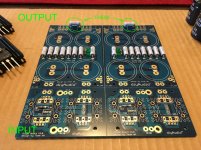
AndrewT, to help clarify, here are pictures of the "snubber" I'm referring to:
It isn't a snubber to stop ringing in the transformer from diode switching; neither is it part of a Zobel network on speaker outputs. It seems to me to be designed with the intention of dampening any ringing that might go back and forth between the output of the power supply and the actual amp circuitry/boards... that's my guess, anyway.
It isn't a snubber to stop ringing in the transformer from diode switching; neither is it part of a Zobel network on speaker outputs. It seems to me to be designed with the intention of dampening any ringing that might go back and forth between the output of the power supply and the actual amp circuitry/boards... that's my guess, anyway.
Attachments
Last edited:
An amplifier output snubber/Zobel network is pretty common practice. In a power supply, I install them on a transformer secondary winding or across rectifiers to control ringing when the rectifiers turn on. (stored charge across the diode junction causes a fast current spike) A generic value is not optimum; I found it necessary to 'tune' values for maximum suppression of ringing at high frequencies. Resistor and capacitor substitution boxes make it fairly easy (try to keep wiring as short as practical).
... there are 1-Ohm resistors R11 and R12 and 0.1uF caps C17 and C18 listed as "output snubber" components.
Remember that R11 and R12 can only "snub" (alternate term: "damp") unwanted ringing, at frequencies sufficiently high that the impedance of series capacitor C17 is less than the resistance of R11. At lower frequencies, the series capacitor acts as a high impedance in series with the damping resistor, preventing the resistor from doing its job: damping.
Let's calculate that particular frequency, in the case where C17 = 0.1uF and R11 = 1.0 ohms:
- R11 = 1 / (2 * pi * f * C17)
- thus
- f = 1 / (2 * pi * R11 * C17) = 1.59 Megahertz
That TI application note looks like it has been written to push audiophile 'buttons', not give wise engineering advice. The circuit seems to have a capacitor across virtually every pair of possible circuit nodes. Best ignored. Assume it is the ramblings of a junior engineer.
There is nothing to 'snub' at the output of a normal linear DC PSU, so no need for a snubber. It does no harm, apart from costing money. People often add them because, like guitar amp 'standby' switches, they know that other people expect to see them.
Snubbers across rectifiers are sometimes useful.
There can be ringing due to the diodes abruptly switching off and the inductance of the transformer.
It isn't just about frequencies above 1/2piRC either, since the cap may be resonating with the transformer or wiring inductance.
For sure there are components in there that Earl Muntz would get rid of, but a trip to the EMC lab might have you putting them back!
Don't forget commercial designs go into residences with powerline internet, triac dimmers and other horrors.
Anyone for a common-mode choke on the input?
... There can be ringing due to the diodes abruptly switching off and the inductance of the transformer.
The diyAudio power supply board includes additional components which snub out ("damp") transformer inductance ringing. In the photograph attached to post #4 of this thread, they are seen at the bottom. "RS1, CS1, CX1" on the left; "RS2, CS2, CX2" on the right.
The component names on this board, match the component names in the "How to snub your transformer without using any mathematics" tutorial document attached to post #1 (here)
Yes Mark, I've got the quasimodo on order and am guessing my RS1 value will be somewhere 10 ohms for my Antek AN-5220 (with caps being 0.01 and 0.15uF). This guesstimate is based on the values for similar transformers. Once I get the quasi jig I'll be able to fire it up and check the scope to get optimal value.
I'll leave my p/s output snubber in place since I've already soldered it onto the board.
I'll leave my p/s output snubber in place since I've already soldered it onto the board.
F6
Uzernaam, any issues with leaving the output snubbers in place?
Yes Mark, I've got the quasimodo on order and am guessing my RS1 value will be somewhere 10 ohms for my Antek AN-5220 (with caps being 0.01 and 0.15uF). This guesstimate is based on the values for similar transformers. Once I get the quasi jig I'll be able to fire it up and check the scope to get optimal value.
I'll leave my p/s output snubber in place since I've already soldered it onto the board.
Uzernaam, any issues with leaving the output snubbers in place?
- Status
- This old topic is closed. If you want to reopen this topic, contact a moderator using the "Report Post" button.
- Home
- Amplifiers
- Power Supplies
- Purpose of output "snubber" on diyaudio p/s board?