What's the ripple like on that sketchy-lookin doohickey?
I mean, all I need is under 30mA, but should I add additional filtering?
It switches at 75 kHz. I use a small RC filter input and power a phono stage with it. Dead quiet. You could also use a small reactor.
So you have too-much AC voltage, and only a few mA of current.
Sure seems like a path to "excess" raw DC then dropped down with a chain of R-C filters.
I recall fine audio preamps that started from 400VDC, dropped to 250VDC for output stage and 150V for input stage. Four R-C filters can do a LOT of filtering if you can accept voltage drop. Not a lot of drop is necessary today since 47uFd caps are only a couple bucks.
This assumes "constant" DC current, which is the case for about all preamps. Big AB power stages are different.
There are ways and means to use lower voltage regulator for higher outputs.
Do a search for Maida regulators which derive the name from Michael Maida of National Semiconductor.
http://www.ti.com/lit/an/snoa648/snoa648.pdf
What sort of current are you needing at this 200 volt level ? I think you mentioned around 30 ma somewhere. Is that all you need.
Do a search for Maida regulators which derive the name from Michael Maida of National Semiconductor.
http://www.ti.com/lit/an/snoa648/snoa648.pdf
What sort of current are you needing at this 200 volt level ? I think you mentioned around 30 ma somewhere. Is that all you need.
Also have a look at this. Figure 12 shows an adjustable series pass regulator that should be persuadable to work down to 200 volts. The series connected R10 and R11 determine the final output.
http://www.next-tube.com/articles/hvs/hvrEn.pdf
http://www.next-tube.com/articles/hvs/hvrEn.pdf
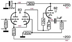
Immediately after power-on, when there is still zero cathode current because the cathode isn't up to operating temperature yet, it looks as though this circuit puts (-200 V DC) on the cathode, and (0 V DC) on the grid.Must say, not too happy with what i found
The GE 12AU7 datasheet I just looked at specifies a maximum of 100 volts DC between heater and cathode.
Repeated application of 200 volts DC between heater and cathode every time the circuit is powered on does not seem like a great idea for valve longevity.
A suitably connected LED (connected from ground to cathode, with the LED anode connected to ground) would clamp the 12AU7 cathode at a couple of volts negative, and protect the heater-cathode insulation until the valve is up to operating temperature and the cathode rises to its normal quiescent DC operating point.
As a bonus, the LED will light up to tell you that the input stage hasn't warmed up yet, and will go out when the valve is ready to amplify. Pick an LED that has enough efficiency to light up on around 4 mA (they're easy to find these days.)
-Gnobuddy
Attachments
Thanks for that information, it is much appreciated.It switches at 75 kHz. I use a small RC filter input and power a phono stage with it. Dead quiet.
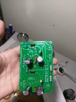
I have one of these boards. I bought it because it seems like a perfect solution for powering a small low-power (couple of watts) valve guitar amp, but I haven't had time to try it out yet.
I'm already using small SMPS to power valve heaters, and they seem to be an excellent solution to that problem. Much better than the traditional one of running wiring carrying large amounts of 60 Hz (or 50 Hz) AC current through the guts of an audio preamp.
-Gnobuddy
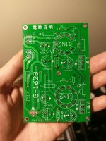
Although I have this circuit board, I've shelved the design for now. That's a pre-amp. But this other one I'm working on is a headphone amp. And I've fried my Bravo Audio v2 by trying to mod in potentiometers for bias adjustment without knowing what I'm doing. I learn by breaking stuff.
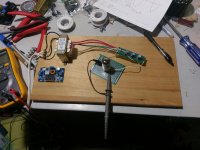
So here are the new tube amp, also wants 200v and 6.3v.
In one photo I'm working on the 6.3v for the tubes, cannibalizing the bravo's tube socket.
I don't plan on mounting the tube sockets on the headphone amp because I'm putting them in an enclosure.
I won't use an IC or switch mode supply for the heaters because there is a +50v applied via a 51k + 150k voltage divider off of the B+. I don't know how a switch mode supply would handle it.
I have an adjustible power supply that I can get to +18v with, and I'll use it to test offsetting the heater voltage. That's what I'm setting up in that picture.
Tube Depot is the shiznit!
Attachments
Most of the switch-mode power supplies I've seen, come with 2-wire AC cords. Since these have no connection to earth at the electrical outlet, the DC output is invariably floating, i.e., not connected to either incoming AC wire (live or neutral).I won't use an IC or switch mode supply for the heaters because there is a +50v applied via a 51k + 150k voltage divider off of the B+. I don't know how a switch mode supply would handle it.
You can check this with an ohmmeter; test for DC continuity from the ground side of the DC output (-ve), to both AC plug prongs. You should find no DC continuity to either plug prong.
(Many of these supplies do actually use two small-value capacitors that connect to the incoming AC plug pins. This means that at high enough frequency, they do not float wrt to the incoming AC. It also means there is a small amount of 60 Hz AC, at a very high source impedance, riding on top of the DC output. Sometimes this is enough to cause annoying hum in audio circuits.)
If you have one of these 2-wire SMPS with a floating output, then applying +50 V DC offset to the ground wire will have no effect on the power supply. Technically you might be increasing the voltage across the insulation barrier by 50 volts at certain instants in time, but any sane manufacturer builds in a considerable safety margin (probably required to get UL certification) for the insulation voltage rating.
Things are different with the SMPS that have a proper IEC inlet and three-wire AC cord. With those, the (-) side of the DC output is usually connected back to the mains earth via the third pin of the AC plug. The DC output is referenced to ground, and so you cannot safely try to apply heater elevation voltage to it (the +50 V you mentioned).
-Gnobuddy
Just to be sure, we're talking about the ground on the DC side...there is no ground on the AC side (only 2 pins, live and neutral). Yes, after you have checked and made sure there is no DC connection between output and AC input prongs, you can almost certainly raise the DC output ground to +50 V without problems. (Often it is already floating at +60V AC. at very high impedance, via the two little capacitors I mentioned earlier.)So like, if I was trying to offset the power supply by 50kv and I raised the ground of the two prong supply to 50kv, it would work?
And I know this was a typo, but again, just to be sure, we're talking about 50 volts....not 50 kilo volts!
I'm just slowly getting over a several-year-long inspiration breakdown.Assuming that the transformer itself didn't have an inspiration breakdown.
Yeah, the insulation in a 120V AC transformer is normally rated for a lot more than 120 V, both for a safety margin, and to be able to deal with normal transients and whatnot.
I'm not an electrician and can't tell you exactly what the standards require, but flash-over ratings for 120V transformers are often in the 1 kV (1000 volts) range.
-Gnobuddy
- Status
- This old topic is closed. If you want to reopen this topic, contact a moderator using the "Report Post" button.
- Home
- Amplifiers
- Power Supplies
- 200V Tube Amp Power Supply