Hi!
I have a R-Core power transformer extracted from an old JVC micro component system and I would like to re-use that for a project. The primary has 4 wires [white, brown, orange and red] and secondary has 2 wires. I found the service manual of the JVC system online and it looks like a switch is used to select 1 of 3 primary wires for 110/127/230 VAC input. I want to use this transformer for a primary voltage of 230VAC but the problem is that I have no clue which two of the 4 wires to pick for 230V input. I have measured the resistances between the primary wires and these are the results:
Can someone help me in identifying which two to use for 230V input?
I have a R-Core power transformer extracted from an old JVC micro component system and I would like to re-use that for a project. The primary has 4 wires [white, brown, orange and red] and secondary has 2 wires. I found the service manual of the JVC system online and it looks like a switch is used to select 1 of 3 primary wires for 110/127/230 VAC input. I want to use this transformer for a primary voltage of 230VAC but the problem is that I have no clue which two of the 4 wires to pick for 230V input. I have measured the resistances between the primary wires and these are the results:
White-Brown: 17Ω
White-Orange: 19.6Ω
White-Red: 54.7Ω
Brown-Orange: 5.8Ω
Brown-Red: 40.9Ω
Orange-Red: 38Ω
White-Orange: 19.6Ω
White-Red: 54.7Ω
Brown-Orange: 5.8Ω
Brown-Red: 40.9Ω
Orange-Red: 38Ω
Can someone help me in identifying which two to use for 230V input?
Attachments
Can someone help me in identifying which two to use for 230V input?
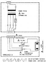
Trace from fuse F1901 to the connector, that's terminal #1.
The opposite end pin on the connector is #4, and that is the highest voltage, 230VAC.
Trace the connector pin #4 to the switch, and set the switch in that position.
Unplug the connector and verify pin #4 connects to the switch output terminal,
by checking with a meter for a short between the two.
Be certain that this switch position is correct before applying power.
Last edited:
Here it is: http://www.vintageshifi.com/repertoire-pdf/pdf/telecharge.php?pdf=Jvc-UXD-88-GD-Service-Manual.pdfIf you let us know the model, we can search the service manual for the colour code.
I had checked earlier but couldn't find any color coding for the wires. Maybe you will have better luck. Thanks for your offer to search. Much appreciated!
Based on your resistance measurements, the order of the taps appears to be white, brown, orange, red.
The resistances do not add up exactly though and that may be because of the resistance of the leads and also the measurements may not be accurate due to not quite perfect connection of the meter to the leads.
However, the white-red connection gives the highest resistance indicating full use of the primary winding so as DF96 proposes, that is probably the 230V connection.
If you have a signal generator, you can send a sine wave to various combinations of primary inputs and measure the input and the output voltages and compare voltage ratios. That would be safer than connecting it to the ac line voltage.
Last edited:
Thanks to everyone who responded.
Sine output: 53.3mVAC
When fed to White-Brown, output at secondary is: 7.9mVAC
When fed to White-Orange, output at secondary is: 6.9mVAC
When fed to White-Red, output at secondary is: 4.6mVAC
When fed to Brown-Orange, output at secondary is: 41.6mVAC
When fed to Brown-Red, output at secondary is: 7mVAC
When fed to Orange-Red, output at secondary is: 8.1mVAC
How do I interpret this?
For a 1kHz sine wave sent through my laptop:If you have a signal generator, you can send a sine wave to various combinations of primary inputs and measure the input and the output voltages and compare voltage ratios. That would be safer than connecting it to the ac line voltage.
Sine output: 53.3mVAC
When fed to White-Brown, output at secondary is: 7.9mVAC
When fed to White-Orange, output at secondary is: 6.9mVAC
When fed to White-Red, output at secondary is: 4.6mVAC
When fed to Brown-Orange, output at secondary is: 41.6mVAC
When fed to Brown-Red, output at secondary is: 7mVAC
When fed to Orange-Red, output at secondary is: 8.1mVAC
How do I interpret this?
Last edited:
I see that you used a 1kHz signal. It is best to use a frequency that the transformer was designed for and that is 50 or 60 Hz, as the 1kHz signal is well above the design frequency of the transformer.
The connection with the lowest voltage output is the connection that makes use of the full primary winding for 230V, the next lowest voltage should be for the 127V, and the highest voltage should be for the 110V:
4.6mV/53.3mV x 230V = 19.85V for red-white
6.9/53.3 x 127 = 16.44 for orange-white
7.9/53.3 x 110 = 16.30 for brown-white
If red was common instead of white:
4.6/53.3 x 230 = 19.85V for white-red
7/53.3 x 127 = 16.68V for brown-red
8.1/53.3 x 110 = 16.72V for orange-red
So there appears to a discrepancy between the 110V/127V and the 230V. This may be due to the 1kHZ input, but I do not know enough about electrical engineering to know whether this discrepancy is due to that. You can redo the test with a 50 or 60 Hz signal to check.
What is still unknown is the current capacity of the transformer. If the output current is much lower than the design current, the output voltage will be higher than the design voltage and vice versa if the output current is higher than the design current.
{snip}....which two of the 4 wires to pick for 230V input.....
The highest resistance. White-Red.
The intermediate taps would be harder to figure. So stay in 230V land.
The tapping resistances are slightly unusual and I would have to agree with DF that they have probably used a thicker wire on part of the primary winding to try to increase efficiency on one of the low voltage windings.From the resistance data I am going to suggest that white is common, brown is 110V, orange is 127V and red is 230V. The lower voltage part of the primary has been wound with thicker wire.
An unusual way to wind and tap for various mains voltages.
Using all three windings in series is the safest way.
And the Mains Bulb Tester saves against damaging accidents.
It was *the* way to wind multi mains voltage transformers for ages, until cutthroat competition forced manufacturers to save a few grams of copper.The tapping resistances are slightly unusual and I would have to agree with DF that they have probably used a thicker wire on part of the primary winding to try to increase efficiency on one of the low voltage windings.
An unusual way to wind and tap for various mains voltages.
Nowadays it´s more common to wind just 2 same wire diameter primaries (you save on readjusting the winding machine and buy just one size of primary wire) which can be used in series for 220/240V or parallel for 110/120V mains, perfect adjustment be d*mned, this is the "one size fits all" era, and a different 100V primary for Japan use only , *or* different 110/120V or 220/240V tapped primaries where the tap can be wound with same wire as the main one, voltage/current difference being on the order of 10% or less; plus a different untapped 100V primary for Japan.
Hey!!!! saving 10 cents per unit in a 10000000 unit run means saving

if you have a 0-100-110-120Vac and dual that,
you end up with primary options of 100, 110 & 120Vac for the low voltage countries
and 200, 210, 220, 230, & 240 for the high voltage countries.
The current difference between the 100, 110 and 120Vac tappings makes it unecessary to reduce the wire diameter for the two higher voltage tappings.
you end up with primary options of 100, 110 & 120Vac for the low voltage countries
and 200, 210, 220, 230, & 240 for the high voltage countries.
The current difference between the 100, 110 and 120Vac tappings makes it unecessary to reduce the wire diameter for the two higher voltage tappings.
- Status
- This old topic is closed. If you want to reopen this topic, contact a moderator using the "Report Post" button.
- Home
- Amplifiers
- Power Supplies
- Help needed to identify which primary wires to use in a transformer