I wouldn't go that far & call your model "real life".but it still covers a good number of real-life situations
Get a dual winding XFMR and build it, you know with a central measurement ground point. Show equal Vripple 1st, then measure current or better yet power factor.
I found one panasonic subwoofer (sb-wa330) that uses this circuit for a 2-step power supply feeding a rsn311w64 ic for the power output.
Check page 12 and 13 on the service manual : http://diagramas.diagramasde.com/audio/Panasonic SB-WA330GCS active subwoofer.pdf
Filter caps were 4700 and 3300 uF and this was a 5.1 channel setup.
Check page 12 and 13 on the service manual : http://diagramas.diagramasde.com/audio/Panasonic SB-WA330GCS active subwoofer.pdf
Filter caps were 4700 and 3300 uF and this was a 5.1 channel setup.
I do not call the model "real life", I just say that the majority of real life loads are either floating (thus inherently balanced) or balanced: amplifiers and opamps circuits fall into that category.I wouldn't go that far & call your model "real life".
A few other circuits require a main (often positive) supply, and an auxiliary supply of opposite polarity.
These will let DC pass through the transformer and aren't suitable candidates for doubler supply: the effects will be unpleasant and unpredictable, and delving into the gory details is a waste of time.
With balanced outputs, the behavior of both circuits will be very similar, if sizing is made fairly: same total CV product for the capacitance, etc.
There will be some minor differences: diodes will see twice the current (but they are 2 instead of 4) and the filter caps will see a ripple at Fmains instead of 2*Fmains.
This in turn will be reflected in the output voltages, and the total output voltage will also be slightly smaller
If you have doubts, feel free to experiment for yourself...
You now admit doubler operation is infact only half wave rectification with all that implies on adding capacitance across the load to compensate ...thus reactive current has increased over the 4 diode version (with equal ripple on the loads ). I'm sorry XFMER utilization is not the same or better for half wave rectification. I don't call it a minor difference on some real designs esp. with small transformers. You can see for yourself on your model if you care to show the output ripple voltages as magnitudes, not simply dismiss it as mains or 2x mains frequencies.
The supply in Question is a dual with a central ground. On your simulation you modified the circuit.. The waveform you showed was a single balanced system operating as full wave which was/is very deceiving, not accurate at all.
Last edited:
That's the problem with simulating designs, at some point you have to build it. That's when the "minor" problems smack you upside the head. Little dual regulated linear supplies are hidden with many gotchas. Starting with this doubler topology youll either have live with higher ripple and more 3T regulator headroom / heatsinks or buying bigger caps, in either case the XFMR will running at hotter VA's.
Last edited:
Ripple frequency is halved = harder to filter.Yes, that's what I ment.
I am not admitting it now: if you cared to read the previous posts, I mentionned it from the very beginning:You now admit doubler operation is infact only half wave rectification....
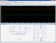
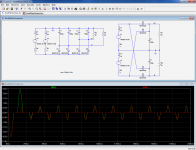
Here are the individual V+ outputs for each case, and also the voltages sum:The differences between a FW doubler and a FW rectifier using a winding of twice the voltage is very subtle indeed, and could be missed in a first analysis, but they do exist: in a FW rectifier, two sets of diodes replenish a single filter capacitor twice per cycle, whereas in a (so-called) FW voltage doubler, two times one diode replenish two caps once per cycle, and the cap voltages are later added.
The result looks superficially similar, but it isn't: adding two half-wave rectifiers isn't equivalent to a true full wave rectifier.
The ripple seen by each half-wave cap is somewhat higher,....
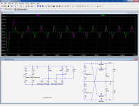
For this situation, the transformers currents are comparable:
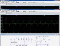
We can increase the filter caps to compensate for the higher ripple:with all that implies on adding capacitance across the load to compensate ...thus reactive current has increased over the 4 diode version (with equal ripple on the loads ). I'm sorry XFMER utilization is not the same or better for half wave rectification. I don't call it a minor difference on some real designs esp. with small transformers. You can see for yourself on your model if you care to show the output ripple voltages as magnitudes, not simply dismiss it as mains or 2x mains frequencies.
This does practically not change the peak currents compared to the previous case (it looks counter-intuitive), because the average output current remains practically identical, as is the diodes conduction angle.
What about the individual ripple voltages? They are now practically identical:
Thus, there is a penalty to be paid (twice the C*V product), but it remains relatively acceptable.
Of course, if you start designing a supply from scratch, it would be silly to opt for the doubler solution, but if you already have a suitable transformer of half the voltage, it is certainly cheaper to use it with a doubler rather than buying a new transformer
Attachments
I saw & agreed with your 1st post. but disagreed with your conclusions about XFMR utilization in later posts.
Now I still have issues with your last sim on the actual circuit. Strangely you added caps to the full wave side correcting the current angle, when we both know it should of been added to the half wave side. right?
Realizing the reactive current is C*dV/dt looking at the ripple voltage
Nothing wrong with the topology. its just not ideal for the smallest iron and copper.
Now I still have issues with your last sim on the actual circuit. Strangely you added caps to the full wave side correcting the current angle, when we both know it should of been added to the half wave side. right?
Realizing the reactive current is C*dV/dt looking at the ripple voltage
I fully agree 100% on this but your sim results and other statements don't support this view.Of course, if you start designing a supply from scratch, it would be silly to opt for the doubler solution,
Of course , also keeping the loads from being too lopsided E.g balanced.but if you already have a suitable transformer of half the voltage, it is certainly cheaper to use it with a doubler rather than buying a new transformer
Nothing wrong with the topology. its just not ideal for the smallest iron and copper.
Last edited:
Of course, if you start designing a supply from scratch, it would be silly to opt for the doubler solution, but if you already have a suitable transformer of half the voltage, it is certainly cheaper to use it with a doubler rather than buying a new transformer
That's exactly the reason why I used it for some preamps.
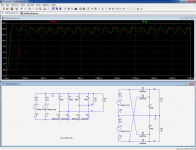
There must be some misunderstanding, because I added the capacitors to the half-wave side (I think), where the voltages have a D suffix:I saw & agreed with your 1st post. but disagreed with your conclusions about XFMR utilization in later posts.
Now I still have issues with your last sim on the actual circuit.Strangely you added caps to the full wave side correcting the current angle, when we both know it should of been added to the half wave side. right?
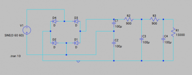
I repost the same picture here, to eliminate possible confusions:
C4 and C5 have been added to compensate for the weakness of the doubler; without them, the comparison is completely fair, ie. identical circuits elements are rearranged in a different manner.
Note that the current angle will only have a minuscule effect on the power factor: most of it stems from the high peak to average ratio, inherent to this type of supply, not the I-V phase shift.
I do not see where.Realizing the reactive current is C*dV/dt looking at the ripple voltage I fully agree 100% on this but your sim results and other statements don't support this view.
The peak current remains ~the same, because the positive slope of the ripple is halved, but the capacitance is doubled.
The area under the peak must remain the same, because the average current is identical.
Note that in all of the cases, the current is measured on one winding, even though the windings are paralleled in the doubler's case. That's to respect the fairness condition:
The primary winding will always see both windings in front of him, be they series or paralleled.
If the loads are unbalanced, the doubler topology should be avoided: some transformers, like loosely packed EI might tolerate it very well, but a high perm toroidal or R-core could be unhappy with only a few % unbalance, and there is no way to know without trying.Of course , also keeping the loads from being too lopsided E.g balanced.
Nothing wrong with the topology. its just not ideal for the smallest iron and copper.
For pure doubler (no GND out) applications, the doubler is only very marginally inferior (for the same components investment).
For dual supplies, the capacitors would need to be larger to keep the same ripple (without impact on the transformer's utilization), but the total component count is 4 against 6, even if the 4 need to be larger.
If one is aware of these limitations, the topology can be useful, especially for DIY purposes (I don't see any valid justification for OEM's)
Attachments
Hello! An old thread but a good one, I figure it's a good place to ask.
I need to get a -100V bias from a 60V power transformer winding and noodling around on LT (which I am very new at) I started playing with this circuit.
I've never seen a bridge used to double before. Is there any reason it shouldn't be used to feed the bottom of a 470K grid resistor? As is, it has .1mA ripple at output.
Thanks
Attachments
i use voltage doublers in all my tube build that are TV scanning tubes, why? because i design and build my own power traffos, and tv power tubes have much lower G2 specs and the voltage doublers provided that convenience....
and do not ask me about regulation, if you know what you are doing, this is never an issue...
and do not ask me about regulation, if you know what you are doing, this is never an issue...
full wave voltage doublers utilize the power traffo secondary for the whole of the 360 deg of the electrical cycle, the full wave center tapped rectifiers only at each 180 deg of the electrical cycle so traffo utilization is much lower than a full wave bridge or a full wave bridge rectifier.....
- Home
- Amplifiers
- Power Supplies
- Why is full wave voltage doubler not used more?