Hi all,
I'm new, both here and in diy in general")
I've decided to assemble my own LPS; I won't say build as I'm just gonna buy some already built parts and put together. But I'm a little bit stuck.
What I need is somewhat similar to below image but only with 2 outputs;
1) 1 x 5V at least 2.5A (for raspberry)
2) 1 x 5V 1A with lowest possible noise (for BOSS dac on top of the raspberry)
I have 230V. I have no ground installed, and I cannot get.
I already ordered 1 board with LT3045 in parallel (1 Ampere) for cleaning up number 2)
I am tempted to buy a dual LT1083 board like this, as that can put some amperes through.
But:
LT1083 has dropout guaranteed at max 1,5
LT3045 has dropout around 0.3V
So it seems to me I could do with a r-core transformer with 7V output like this one. But its much easier to find a 9V transformer like this one.
So, would there be any downsides to using a 9V r-core - would anything get hotter?
I've seen somewhere (probably on an ebay add) that LT1083 works best with 3-5V dropout, but I am in doubt if that is correct.
Anyone have a hint as to what transformer to use (7v or 9V), or if I can make better choices anywhere?
Thanks a lot

I'm new, both here and in diy in general
I've decided to assemble my own LPS; I won't say build as I'm just gonna buy some already built parts and put together. But I'm a little bit stuck.
What I need is somewhat similar to below image but only with 2 outputs;
1) 1 x 5V at least 2.5A (for raspberry)
2) 1 x 5V 1A with lowest possible noise (for BOSS dac on top of the raspberry)
I have 230V. I have no ground installed, and I cannot get.
I already ordered 1 board with LT3045 in parallel (1 Ampere) for cleaning up number 2)
I am tempted to buy a dual LT1083 board like this, as that can put some amperes through.
But:
LT1083 has dropout guaranteed at max 1,5
LT3045 has dropout around 0.3V
So it seems to me I could do with a r-core transformer with 7V output like this one. But its much easier to find a 9V transformer like this one.
So, would there be any downsides to using a 9V r-core - would anything get hotter?
I've seen somewhere (probably on an ebay add) that LT1083 works best with 3-5V dropout, but I am in doubt if that is correct.
Anyone have a hint as to what transformer to use (7v or 9V), or if I can make better choices anywhere?
Thanks a lot
Last edited:
The higher voltage transformer would give a little higher DC voltage, almost 13 volts vs 10 volts.
The excess voltage is 'lost' as heat within the regulator. For example the 13v DC rail would dissipate 20 watts @ 5 volt and 2.5 A and the 10 volt rail would dissipate just 12.5 watts. So a big difference.
Things to consider... the quoted dropout voltage means that the minimum trough in the ripple voltage must not fall below this value. You also have to design for worst case scenario such as if your mains voltage is at the lower limit.
5 volt at high current for PC use is ideally suited to an SMPS rather than a linear reg tbh.
As to 5 vs 9 volt transformers. I would say if you really are pulling 2.5 amps then the higher voltage option is safer for guaranteed performance but you take a big hit on excess heat.
The higher voltage transformer would give a little higher DC voltage, almost 13 volts vs 10 volts.
The excess voltage is 'lost' as heat within the regulator. For example the 13v DC rail would dissipate 20 watts @ 5 volt and 2.5 A and the 10 volt rail would dissipate just 12.5 watts. So a big difference.
Things to consider... the quoted dropout voltage means that the minimum trough in the ripple voltage must not fall below this value. You also have to design for worst case scenario such as if your mains voltage is at the lower limit.
5 volt at high current for PC use is ideally suited to an SMPS rather than a linear reg tbh.
As to 5 vs 9 volt transformers. I would say if you really are pulling 2.5 amps then the higher voltage option is safer for guaranteed performance but you take a big hit on excess heat.
Excellent Mooly, thanks a lot. So I have to multiply the AC output of transformer by 1.4, to get the DC voltage? (I've heard rumors of a factor of 1.4, but haven't found out where to apply it). I've wondered what happened to the excess voltage, naturally heat is the answer
I don't want too much heat, contradicts some of the point of using a class D amp (icepower) in the first place.I will probably never go near the 2.5A, its just for worst case. I will not use usb and wifi on the raspberry, so probably 1.5A max is a better estimate. My mains seems to be at 228V, hopefully not swinging too wildly (I would expect it to be steady). People seem to say the dac definetly benefits from a LPS, and that a raspberry benefits too.
Am I wrong that the dropout voltage is the minimum required difference between in and out? I believe that explanation is written many places, but of course that does'nt make it correct
So in my view if I take a normal 6.3V transformer the calc would be
6.3VAC * 1.4 = 8,82VDC
8,82VDC - 2VDC (the sum of dropouts for LT1083 and LT3045) = 6,82
So I'm still on the good side of 5V, and with minimal heat.
Would that calculation be nonsense? Sorry for many questions...
Last edited:
Yes, the dropout voltage is the minimum voltage the regulator has to have 'across it' in order to function.
This will help show the relationship of voltages and currents for transformers and what happens when you rectify the voltage:
RECTIFIER TRANSFORMER CALCULATION
In practice... the transformer voltage is quoted at full load current when working into a resistive load.
1.414, the magic number is simply the square root of root. So 9vac gives 9*1.414 which is 12.7 volts DC.
We have another complication... the voltage dropped by the bridge rectifier. This is around 1.4 volts (two 0.7 volt diode drops) and so that reduces the available voltage a little.
Also, the transformer voltage can be significantly higher at lower currents than the transformer is rated for. That factor is sometimes quoted as the 'regulation' of the transformer and is given as a percentage such as 6%. That means the voltage is that much higher at low current.
Small transformer have much worse (higher percentage) than large ones.
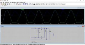
Have a look at this. Here is a 9 volt (so 12.7 volt peak) transformer feeding a bridge rectifier.
Notice how the peak voltage equals the transformer peak voltage less the diode volt drops.
Also notice the ripple voltage across the cap. That voltage must never dip below the regulator drop out voltage.
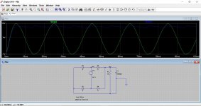
In the second picture we have made the cap much larger to reduce ripple.
Notice how the peak voltage equals the transformer peak voltage less the diode volt drops.
Also notice the ripple voltage across the cap. That voltage must never dip below the regulator drop out voltage.
In the second picture we have made the cap much larger to reduce ripple.
Attachments
Thanks a lot again, thats very pedagogicalHave a look at this. Here is a 9 volt (so 12.7 volt peak) transformer feeding a bridge rectifier.
Notice how the peak voltage equals the transformer peak voltage less the diode volt drops.
Also notice the ripple voltage across the cap. That voltage must never dip below the regulator drop out voltage.
In the second picture we have made the cap much larger to reduce ripple.
I can't find any regulation percentages for the China r-cores I'm looking at. But I hope that since its downregulated it won't matter much.
So will I overlook anything if I do like this?
An externally hosted image should be here but it was not working when we last tested it.
With
LT3045
LT1083
R-core 56W
I have to check if that dual LT1083 can take just 1 x 6.3V in, I can't find a transformer with 2 x 6.3V and A >= 2.5. And also need to check if each output is independently adjustable.
Last edited:
Its to tight for comfort imo.
6.3 Vac is only going to give around 7.5 volts DC under heavy loading and with a large reservoir cap.
The LT 3045 is only a 0.5 amp device.
http://cds.linear.com/docs/en/datasheet/3045f.pdf
The LT1083
http://cds.linear.com/docs/en/datasheet/108345fh.pdf
has a 1 volt dropout.
I think the 6.3 volt transformer is to tight.
Thanks. The LT3045 I bought (and linked) is dual so it can handle up to 1A (according to seller - he seems reliable). It seems LT3045 only has 0,3V dropout. The reason for LT3045 is that it seems unique with extremely low noise.
But your worry is definetly noted I will reconsider
But your worry is definetly noted
I will reconsider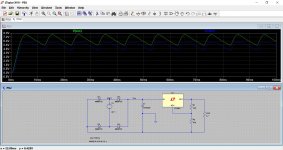
The transformer regulation of smaller Rcores is often around the 15% to 18% value. Seems about the same as smaller EI transformers rather than the slightly lower regulation values seen in Toroid transformers.Thanks a lot again, thats very pedagogical
I can't find any regulation percentages for the China r-cores I'm looking at. But I hope that since its downregulated it won't matter much.
So will I overlook anything if I do like this?
An externally hosted image should be here but it was not working when we last tested it.
With
LT3045
LT1083
R-core 56W
I have to check if that dual LT1083 can take just 1 x 6.3V in, I can't find a transformer with 2 x 6.3V and A >= 2.5. And also need to check if each output is independently adjustable.
That's pretty much it, yes You need that slightly higher input voltage.
Although it looks pretty dramatic on the graph, the headroom needed is only a volt or so if you look carefully. The 6.3 volt transformer can't achieve that though, not when the troughs in the ripple voltage are taken into account.
This was with shottky rectifiers too which also minimise lost voltage.
To play safe you need the 9 volt tranny. Also as your currents are high you also have to factor in wiring loses and so on and they all add up, a few tens of millivolts here, hundred millivolts there if you have a fuse in circuit (and you should).
Back later
You need that slightly higher input voltage.Although it looks pretty dramatic on the graph, the headroom needed is only a volt or so if you look carefully. The 6.3 volt transformer can't achieve that though, not when the troughs in the ripple voltage are taken into account.
This was with shottky rectifiers too which also minimise lost voltage.
To play safe you need the 9 volt tranny. Also as your currents are high you also have to factor in wiring loses and so on and they all add up, a few tens of millivolts here, hundred millivolts there if you have a fuse in circuit (and you should).
Back later
The transformer regulation of smaller Rcores is often around the 15% to 18% value. Seems about the same as smaller EI transformers rather than the slightly lower regulation values seen in Toroid transformers.
That's pretty much it, yes
Although it looks pretty dramatic on the graph, the headroom needed is only a volt or so if you look carefully. The 6.3 volt transformer can't achieve that though, not when the troughs in the ripple voltage are taken into account.
This was with shottky rectifiers too which also minimise lost voltage.
To play safe you need the 9 volt tranny. Also as your currents are high you also have to factor in wiring loses and so on and they all add up, a few tens of millivolts here, hundred millivolts there if you have a fuse in circuit (and you should).
Back later
Back at 20W heat then
Also thanks for comment Andrew
I am probably thick skulled but can I ask how you estimated that (the 7.5)?Its to tight for comfort imo.
6.3 Vac is only going to give around 7.5 volts DC under heavy loading and with a large reservoir cap.
It seems 16% lower than expected, so if this is the regulation you compensate for I don't understand why it is necessary to adjust for this at full load at all, if the nominal voltage also is indicated under full load. Seems to me it would be necessary to adjust for regulation under small load, and adjust it upwards. I clearly have it wrong

The transformer regulation is something you have no control over and is simply the amount by which the secondary voltage will rise at light loading. At full load the voltage should be equal to the rated voltage.
So 6.3 volts multiplied by 1.414 (root 2) gives 8.9 volts peak. When we apply that to a bridge rectifier we have to include the two (because there are always two diodes conducting) volt drops of each diode. A normal silicon device drops around 0.7 volts across it when it conducts. So we subtract 1.4 from 8.9 to give 7.5 volts DC.
6.3 volts is the stated voltage of the transformer and is correct when the transformer is loaded. When drawing little current that voltage will rise by the 'regulation percentage' of the transformer.
This shows typical regulation values for small transformers. The higher the VA rating (a bigger current transformer) the lower (better) the regulation percentage figure.
Attachments
Thanks, yes thats how I understand it too. But the LT1083 will rectify and regulate for 1.5V, so everything is done at the 7.5v level, nothing further needed (well, the line with the LT3045 needs 0.3 or 0.5V of those), but still much more than 5V left. Ah well I don't have to understand it when you say it won't work..The transformer regulation is something you have no control over and is simply the amount by which the secondary voltage will rise at light loading. At full load the voltage should be equal to the rated voltage.
So 6.3 volts multiplied by 1.414 (root 2) gives 8.9 volts peak. When we apply that to a bridge rectifier we have to include the two (because there are always two diodes conducting) volt drops of each diode. A normal silicon device drops around 0.7 volts across it when it conducts. So we subtract 1.4 from 8.9 to give 7.5 volts DC.
6.3 volts is the stated voltage of the transformer and is correct when the transformer is loaded. When drawing little current that voltage will rise by the 'regulation percentage' of the transformer.
This shows typical regulation values for small transformers. The higher the VA rating (a bigger current transformer) the lower (better) the regulation percentage figure.
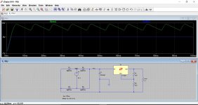
Look at the ripple voltage in post #9. That is the problem. The DC voltage 'peaks' at around 7.5 volts but then falls as the voltage has to be supplied by the reservoir cap until the next half cycle comes along and tops the cap up again.
So when we draw current from the DC rail the ripple voltage increases. Look at the dips in the voltage that go below the regulator drop out voltage. Those are the problem.
The smooth DC when lightly loaded has changed to 'dirty' DC with lots of ripple as we draw higher current.
Does that make sense
So when we draw current from the DC rail the ripple voltage increases. Look at the dips in the voltage that go below the regulator drop out voltage. Those are the problem.
The smooth DC when lightly loaded has changed to 'dirty' DC with lots of ripple as we draw higher current.
Does that make sense
- Status
- This old topic is closed. If you want to reopen this topic, contact a moderator using the "Report Post" button.
- Home
- Amplifiers
- Power Supplies
- 9V or 7V r-core transformer for 5V out