On the Hammond site.
That sheet has real problems. Note particularly the Capacitor Input Load conditions show different Peak and Average values. We use a capacitor to make average stay "near" peak. We need to know the R-C values to know how the average fall shy of the peak.
I asked Hammond to explain. They kindly told me they got it somewhere on the web, were not responsible for its content, do not give design advice, and suggest professional design help.
For more fun: Hammond specs a CT winding as the full voltage end-to-end (the way they sell them) but many newer plans will say 22V+22V or 22V-0-22V. So some numbers are half/twice what you expect.
For my self-pleasure(?), I marked-up the sheet for the circuits I know and care about.
cool! now, how I make my 1400mA transformer with 2 wires output 0-22vAC spit 22vDC at a minimum draw of 1100mA ?
some said i'd need a tranny or an IC to regulate and bla bla bla... i thought it would be something simple as putting some diodes to rectify, then some resistor to drop voltage back to 22 and then filter cap to filter the pulses...
plz help

Are you capable of making a fused and safe and properly earthed linear power supply that will connect to the AC mains?
Other people may play with your rig.
i didnt got it... whatcha mean?
yes, internally the pedal converts the 22vdc into a higher voltage
Then you should question the wisdom of designing a super duper linear supply only to have it feed a switcher that will be much less clean and generate much more noise.
Jan
cool! now, how I make my 1400mA transformer with 2 wires output 0-22vAC spit 22vDC at a minimum draw of 1100mA ?
some said i'd need a tranny or an IC to regulate and bla bla bla... i thought it would be something simple as putting some diodes to rectify, then some resistor to drop voltage back to 22 and then filter cap to filter the pulses...
plz help
Listen... and yes the 'average' DC voltage info in that pdf is misleading as PRR points out, however the current relationships are correct.
Your 1.4A transformer is under rated to supply 1.1 A DC continuously. You need a 1.8A secondary as a minimum. Put another way and you multiply the DC current draw by 1.61 to arrive at the required AC rating. 1.1*1.61= 1.77 That would be a minimum. So ideally you should be looking at somewhere around '50VA' (volt-amps) rating as a minimum. That is how most transformers are specified.
So what is going to happen...
The transformer may run hot. How hot or whether hot enough to fail depends on how generous the designers have been, the mechanism for this being partly caused by the core saturating (not enough metal in there to support the magnetic field needed for your current draw. Also thickness of wire used (copper losses)).
A diode bridge and reservoir cap gets you around 30 volts DC. A resistor is no good for dropping the voltage because the voltage dropped depends on the current drawn.
We know there must be a DC/DC convertor in the pedal. There will be times when that convertor see the full 30 volts (even with a resistor) and that could be enough to cause failure. Power on and power off are times most likely for that scenario.
A resistor is also a really poor way of 'regulating' a voltage.
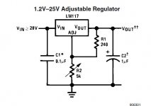
You need a proper voltage regulator and the LM317 has been mentioned. That is good for 1.5A and would generate a clean and stable 22 volt supply.
Attachments
Hi all,
... I have just briefly skimmed the thread and so may have missed something. But when looking at the case for the pedal psicopanque has linked to (#12) I am thinking that it looks like a plastic"y" cabinet - and also of a modest size - and it doesn't look as if it will be able to dissipate (anywhere?) near 1.1 A * 22 volts (24 watts). Just a thought ...
Cheers,
Jesper
A PS.: A slightly improved version of the LM317T I believe is to connect a 10uF capacitor across R2 (from adj to gnd) in the image Mooly has posted. I personally would also add more capacitance on the input side (e.g. 2200 uF) since current draw may change and this may help the regulator to work in "a stable way" (a reservoir as Mooly mentioned).
Last edited:
You could modify the supply to ground the zero volt line.
the original switching PS is all sealed without screws, its not serviceable
Then you should question the wisdom of designing a super duper linear supply only to have it feed a switcher that will be much less clean and generate much more noise.
Jan
you say it because it seems you havent took a look @ the device's schematic, why would you bother flabbing such words of you aint gonna help design the PS -_-
Listen... and yes the 'average' DC voltage info in that pdf is misleading as PRR points out, however the current relationships are correct.
Your 1.4A transformer is under rated to supply 1.1 A DC continuously. You need a 1.8A secondary as a minimum. Put another way and you multiply the DC current draw by 1.61 to arrive at the required AC rating. 1.1*1.61= 1.77 That would be a minimum. So ideally you should be looking at somewhere around '50VA' (volt-amps) rating as a minimum. That is how most transformers are specified.
So what is going to happen...
The transformer may run hot. How hot or whether hot enough to fail depends on how generous the designers have been, the mechanism for this being partly caused by the core saturating (not enough metal in there to support the magnetic field needed for your current draw. Also thickness of wire used (copper losses)).
A diode bridge and reservoir cap gets you around 30 volts DC. A resistor is no good for dropping the voltage because the voltage dropped depends on the current drawn.
We know there must be a DC/DC convertor in the pedal. There will be times when that convertor see the full 30 volts (even with a resistor) and that could be enough to cause failure. Power on and power off are times most likely for that scenario.
A resistor is also a really poor way of 'regulating' a voltage.
You need a proper voltage regulator and the LM317 has been mentioned. That is good for 1.5A and would generate a clean and stable 22 volt supply.
thks mooly, i'll return the transformer to the dealer then
Hi all,
... I have just briefly skimmed the thread and so may have missed something. But when looking at the case for the pedal psicopanque has linked to (#12) I am thinking that it looks like a plastic"y" cabinet - and also of a modest size - and it doesn't look as if it will be able to dissipate (anywhere?) near 1.1 A * 22 volts (24 watts). Just a thought ...
Cheers,
Jesper
A PS.: A slightly improved version of the LM317T I believe is to connect a 10uF capacitor across R2 (from adj to gnd) in the image Mooly has posted. I personally would also add more capacitance on the input side (e.g. 2200 uF) since current draw may change and this may help the regulator to work in "a stable way" (a reservoir as Mooly mentioned).
yes, it draws that much and yes, I agree about larger filter capacitance
“I believe that this instinct to perpetuate useless work is, at bottom, simply fear of the mob. The mob (the thought runs) are such low animals that they would be dangerous if they had leisure; it is safer to keep them too busy to think.” George Orwell, Down and Out in Paris and London, p. 119
Mona
Monayou say it because it seems you havent took a look @ the device's schematic, why would you bother flabbing such words of you aint gonna help design the PS -_-
Well, you are looking for less noise and more clean power for your unit no? So if you design a very clean and noise free 22V supply and use that to feed a switcher that generates the high voltage for the tube, you still get all the junk of the switcher, no?
Or am I missing something?
Jan
Interesting. People often quote this 'Hammond' sheet and regard it as authoritative. Perhaps Hammond should have done the original author the courtesy of attribution? Then we would know where to send corrections to.PRR said:I asked Hammond to explain. They kindly told me they got it somewhere on the web, were not responsible for its content, do not give design advice, and suggest professional design help.
A little courtesy shown to experienced people might get you more help. This is not a free consultancy service from world-class engineers, but there are world-class people on here and they are willing to help newcomers do DIY if you ask them nicely.Psicopanque said:you say it because it seems you havent took a look @ the device's schematic, why would you bother flabbing such words of you aint gonna help design the PS -_-
i didnt got it... whatcha mean?
I mean, you appear to want to somehow electrically connect parts to make a power supply that connects to the AC mains. If you buy such a product, then it must have passed a range of safety regulations and tests to allow it to be used by the public - otherwise it could be dangerous, as evidenced by news stories of unsafe imported equipment which sadly has caused electrocution or fire.
A DIY AC mains supply does implicitly require the constructor to have enough capability to make and test a safe product - or sadly the risk could be one less guitarist in the world.
If somebody knocked on my door and asked for help to 'design' an AC mains power supply, then safety and capability would be the first queries I'd raise.
Well, you are looking for less noise and more clean power for your unit no? So if you design a very clean and noise free 22V supply and use that to feed a switcher that generates the high voltage for the tube, you still get all the junk of the switcher, no?
Or am I missing something?
Jan
the SPS outside the pedal is junk because was designed without grounding because the designer probably lives somewhere within a good electrical net
the SPS inside the pedal is noiseless high grade
Interesting. People often quote this 'Hammond' sheet and regard it as authoritative. Perhaps Hammond should have done the original author the courtesy of attribution? Then we would know where to send corrections to.
A little courtesy shown to experienced people might get you more help. This is not a free consultancy service from world-class engineers, but there are world-class people on here and they are willing to help newcomers do DIY if you ask them nicely.
you say it because you wanted to criticise me since i am being kind to everyone except smartasses that come in the forum with useless flabble in order to tease and flame the newcomers
I mean, you appear to want to somehow electrically connect parts to make a power supply that connects to the AC mains. If you buy such a product, then it must have passed a range of safety regulations and tests to allow it to be used by the public - otherwise it could be dangerous, as evidenced by news stories of unsafe imported equipment which sadly has caused electrocution or fire.
A DIY AC mains supply does implicitly require the constructor to have enough capability to make and test a safe product - or sadly the risk could be one less guitarist in the world.
If somebody knocked on my door and asked for help to 'design' an AC mains power supply, then safety and capability would be the first queries I'd raise.
oh, i see... i don't mind being eletrocuted to death, the sad part, as you mentioned is if someone willing to live asks to play with my rig, and i totally agree with you regarding others safety, i'd never forgive myself if my mistakes harm others
the SPS outside the pedal is junk because was designed without grounding because the designer probably lives somewhere within a good electrical net
the SPS inside the pedal is noiseless high grade
You keep trying to make this point, but in reality this is a typical and superior design because it allows you to avoid a ground loop. Are you completely oblivious to the $$$ pedalboard power supplies where each individual supply is completely isolated?
Last edited:
the SPS outside the pedal is junk because was designed without grounding because the designer probably lives somewhere within a good electrical net
Actually it probably is a high grade one, double-insulated, not needing a ground meaning you will have no ground loop issues.
Edit: I see leadbelly made the same point.
Jan
- Status
- This old topic is closed. If you want to reopen this topic, contact a moderator using the "Report Post" button.
- Home
- Amplifiers
- Power Supplies
- Help me design a Noiseless Linear P/S