THIS POST HAS BEEN EDITED TO BETTER ILLUSTRATE THE DANGER ASSOCIATED WITH A TRANSFORMERLESS POWER SUPPLY. PLEASE READ THE WARNING CAREFULLY BEFORE ATTEMPTING ANY NON-ISOLATED CIRCUIT LIKE THIS.
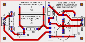
I decided to design a low voltage (e.g. 12 Vdc) single-rail power supply board for some upcoming projects that I could build with parts that I have on hand. Since I am interested in exploring transformerless power supplies (TPS) and because a TPS has many similarities to a linear power supply after the rectifier, I combined both types on a single 2x4" PCB. See attached screen capture of the layout.
FIRST, SOME CLEAR WARNING ABOUT TRANSFORMERLESS POWER SUPPLIES...
Portions of these types of circuits are essentially a direct connection back to your household wiring. Never allow this kind of circuit to be exposed when powered, and never touch a circuit before allowing it to completely discharge. Even without mains power applied, a capacitor that has been connected across mains voltages may still contain high voltage, possibly enough to kill you, unless the charge has been drained away by some means. Never use a transformerless power supply to power anything that will connect externally or is mounted in the chassis such as LEDs, switches, input or output jacks, etc. In a worst case situation fault condition circuit mains voltage can pass down the circuit. This can cause components to explode or spark, etc. A fuse has been included in the circuit below to quickly cut power in the event of such a failure, or a short circuit, however this does not offer foolproof protection and is only intended to prevent widespread fire, etc. Use only in a grounded chassis with a 3-prong grounded and properly wired plug. Some households may have improper wiring in which live and neutral wiring is reversed inside the wall. Do not assume neutral is at ground potential! Further and more complete warning information is available here:
Rod Elliot: Transformerless Power Supplies
As noted on the board, it can be linear or transformerless depending on how it is populated. When used as a linear supply, the transformer is off board. As a TPS, the AC input is connected to AC mains.
Rectification is via full bridge. The builder can employ CRC filtering via C3-R3-C4 and has the option to populate zener Z1 to limit the output voltage.
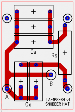
Since I have recently become aware of a proper snubber design, I came up with an optional "HAT" that holds the components for a CRC type snubber (a la Mark Johnson) that can be used when the board is configured as a linear PS. The snubber hat PCB sits on top of the portion of the board where the high-voltage side components of the TPS (caps C1, C2 and resistors R1, R2) would be populated. If no snubber is desired, the builder simply populates a jumper between points A and B on the PS board (see attached PS board image).
The combination of the PS board and optional snubber HAT should suit many types of housekeeping and audio power supplies that a DIY builder might require.
I decided to design a low voltage (e.g. 12 Vdc) single-rail power supply board for some upcoming projects that I could build with parts that I have on hand. Since I am interested in exploring transformerless power supplies (TPS) and because a TPS has many similarities to a linear power supply after the rectifier, I combined both types on a single 2x4" PCB. See attached screen capture of the layout.
FIRST, SOME CLEAR WARNING ABOUT TRANSFORMERLESS POWER SUPPLIES...
Portions of these types of circuits are essentially a direct connection back to your household wiring. Never allow this kind of circuit to be exposed when powered, and never touch a circuit before allowing it to completely discharge. Even without mains power applied, a capacitor that has been connected across mains voltages may still contain high voltage, possibly enough to kill you, unless the charge has been drained away by some means. Never use a transformerless power supply to power anything that will connect externally or is mounted in the chassis such as LEDs, switches, input or output jacks, etc. In a worst case situation fault condition circuit mains voltage can pass down the circuit. This can cause components to explode or spark, etc. A fuse has been included in the circuit below to quickly cut power in the event of such a failure, or a short circuit, however this does not offer foolproof protection and is only intended to prevent widespread fire, etc. Use only in a grounded chassis with a 3-prong grounded and properly wired plug. Some households may have improper wiring in which live and neutral wiring is reversed inside the wall. Do not assume neutral is at ground potential! Further and more complete warning information is available here:
Rod Elliot: Transformerless Power Supplies
As noted on the board, it can be linear or transformerless depending on how it is populated. When used as a linear supply, the transformer is off board. As a TPS, the AC input is connected to AC mains.
Rectification is via full bridge. The builder can employ CRC filtering via C3-R3-C4 and has the option to populate zener Z1 to limit the output voltage.
Since I have recently become aware of a proper snubber design, I came up with an optional "HAT" that holds the components for a CRC type snubber (a la Mark Johnson) that can be used when the board is configured as a linear PS. The snubber hat PCB sits on top of the portion of the board where the high-voltage side components of the TPS (caps C1, C2 and resistors R1, R2) would be populated. If no snubber is desired, the builder simply populates a jumper between points A and B on the PS board (see attached PS board image).
The combination of the PS board and optional snubber HAT should suit many types of housekeeping and audio power supplies that a DIY builder might require.
Attachments
Last edited:
Power supplies that rectify mains voltage is not discussed here in these forums, considering safety protocols. Expect a moderator to likely close out this thread shortly.
-----------------------------------------------------------------------Rick.........
So a discussion is "not allowed"? What is the harm in that?
I am aware of the safety issues. I was not aware of any rule about posting about it.
And if there is such a rule, than DIY Audio Store should be prevented from selling its "soft-start" board. That is mains powered, aint it now? You can see the schematic here:
DIY AUDIO SOFT-START SCHEMATIC (IT'S MAINS POWERED
 )
)It would seem to be a bit hypocritical to ban threads about transformerless power supplies while selling a PCB that uses one!
-----------------------------------------------------------------------Charlie
Last edited:
See note 2 in the rules
OK, it says I should "include a warning in the thread that adequately explains these risks"
I'm happy to edit my initial post with a big fat warning about electrocuting yourself, or any other warning that the "mods" would be happy with.
Squelching discussion will only lead to an information vacuum and SOME people may try to "experiment". IMHO it's better to know all about it, than to hide the truth because there is danger involved.
Last edited:
It specifically says transformerless supplies are not to be discussed
My circuit, with a relay connected to it (which is how I intend to use it when it is built as a TPS) is essentially the same thing as the DIY Audio Store soft-start PCB, just not all on one PCB. Yet that is discussed on, and even SOLD by, this very web site. Seems to be a rather fuzzy rule...

We are looking at this topic again. It appears that these supplies are in common use for consumer equipment and it can be expected that many of our members will be in contact with them. Since we would like to maintain our live membership numbers, we may address these types of supplies in the near future. This would be the best way to educate and keep some of our members from winning a Darwin award.
For now this thread is fine, but please continue to indicate unsafe areas of these circuits in your normal flow of posts.
-Chris
I have finally received the PCBs I ordered for the power supply. I hope to build one up next week and test the TPS configuration along with the relay board that I recently developed for startup and other housekeeping tasks.
I also hope to build up a board as a linear power supply with snubber, since that will let me finally do some measurements with my Quasimodo jig. I have been busy doign some remodeling demo work over the past week or so, but there is an upcoming pause in that project and I should have some time for DIYaudio again.
I also hope to build up a board as a linear power supply with snubber, since that will let me finally do some measurements with my Quasimodo jig. I have been busy doign some remodeling demo work over the past week or so, but there is an upcoming pause in that project and I should have some time for DIYaudio again.
Power supplies that rectify mains voltage is not discussed here in these forums, considering safety protocols. Expect a moderator to likely close out this thread shortly.
-----------------------------------------------------------------------Rick.........
Please read the NEW rules Richard.

I have finally received the PCBs I ordered for the power supply. I hope to build one up next week and test the TPS configuration along with the relay board that I recently developed for startup and other housekeeping tasks.
I also hope to build up a board as a linear power supply with snubber, since that will let me finally do some measurements
If you hope to observe the ringing of your transformer "in situ" , connected up the the actual diodes and the actual filter cap(s) and the actual load current, I offer two suggestions that will help you get a larger-amplitude and more stable trace on your scope:
- Temporarily install some known-awful, lots-of-ringing diodes to make the measurements. Then after optimal snubbing has been accomplished, swap back to the diodes your circuit designer specified. Since the PCB layout seems to show a GBU/GBJ bridge rectifier package, I suggest GBU2510 -- it was the second worst of all 48 diodes tested.
- Connect a load to the power supply which represents the worst case maximum current it will be called upon to deliver. Greater current "I" means greater rate-of-change dI/dt, which means the diodes smack the bell very hard, which means the bell will ring loud and clear.
Thanks for the advice, Mark. I might try that "in situ" approach. What about using the QM jig to drive the transformer+PCB with the components on thhe PCB instead of on the QM jig?
I know those GBU type inline bridges are pretty "ringy" but I have over 100 of them!
I will be using an analog scope so I am also planning to adjust the frequency of the stimulus so that I can pick it up better on the CRT.
I know those GBU type inline bridges are pretty "ringy" but I have over 100 of them!
I will be using an analog scope so I am also planning to adjust the frequency of the stimulus so that I can pick it up better on the CRT.
Last edited:
WARNINGS can't stop stupid persons from doing bad things. I have read the rules. I have been working on AC LINE EQUIPMENT my hole career. AC/DC radios, TV and beyond. My bench has AC power line isolation transformers for 120/240 from 100w to >4kVA. Debug of line powered DUT can be deadly and so can drunk driving. Duke
Hi Duke,
You can still create a shock hazard running equipment on an isolation transformer. Never let your guard down and do keep your left hand in your pocket.
-Chris
So true. Another way of putting this is an idiot looking for a place to be stupid. Or, a Darwin award winner.WARNINGS can't stop stupid persons from doing bad things.
Can't be stressed strongly enough.My bench has AC power line isolation transformers ...
You can still create a shock hazard running equipment on an isolation transformer. Never let your guard down and do keep your left hand in your pocket.
-Chris
That testing arrangement is conspicuously absent from the Quasimodo manual. But you certainly could try it yourself and find out what happens. The worst that can possibly happen is, you burn out the MOSFETs and the injection capacitor Cx on your CheapoModo / Quasimodo. $3.00 worth of replacement parts and 20 minutes of soldering later, you are back in business. If it gives the results you want, yay. If it does not, you can always unsolder the transformer leads and retreat to conventional test methods: optimize the snubber(s) using the arrangement mentioned in the Quasimodo manual.What about using the QM jig to drive the transformer+PCB with the components on thhe PCB instead of on the QM jig?
That testing arrangement is conspicuously absent from the Quasimodo manual. But you certainly could try it yourself and find out what happens. The worst that can possibly happen is, you burn out the MOSFETs and the injection capacitor Cx on your CheapoModo / Quasimodo. $3.00 worth of replacement parts and 20 minutes of soldering later, you are back in business. If it gives the results you want, yay. If it does not, you can always unsolder the transformer leads and retreat to conventional test methods: optimize the snubber(s) using the arrangement mentioned in the Quasimodo manual.
Hi Mark,
I couldn't quite glean your tone in the post above, so I wanted to ask you specifically about using the QM jig plus my PS board and snubber hat to set Rs (I would already populate the CRC snubber caps on the PS board). The PS board and snubber hat layout are shown in post 1. If you were truly warning me about the possibility of doing some harm to the QM jig... I don't quite see how that might happen. I would only populate the snubber hat, the fuse, and the bridge rectifier - nothing downstream of that (e.g. no smoothing caps, load, etc.). When that is connected to the offboard transformer it seems to be essentially the same circuit as your QM jig has onboard. Can you please clarify your post and thoughts about this arrangement?
- Status
- This old topic is closed. If you want to reopen this topic, contact a moderator using the "Report Post" button.
- Home
- Amplifiers
- Power Supplies
- linear or transformerless power supply board with snubber hat