Try it.
I don't see how it can possibly do more than $3.00 worth of damage, and if any damage does occur, it is on your Quasimodo test board, not your power supply.
If no damage occurs, the test you propose might even produce an oscilloscope signal which lets you dial in a snubbing resistance that gives zeta=1.0. If so, cheer and say "Yay!". If not, you can always go back to the more standard Quasimodo procedure as described in the manual.
Summary: it's a low risk experiment, why not try it and learn something new? Maybe simulation would give some insight before entering the testing laboratory.
I finally have the boards in hand. I'm checking the fit of some components... I should have made those thru-holes for C1 and C2 a bit larger. Luckily I can barely squeeze the component leads thru so I can at least build one to test. I also forgot to order the fuse clips, so that will set me back a few days until they arrive.
In the meantime, I thought I would talk a little bit more about the transformerless power supply (TPS). If we think about it in a simplistic way, a TPS is an AC source with a current limiting element that is connected to a bridge rectifier and then smoothing caps. The output is then (must be) connected to a load for the TPS to function properly. If you consider the bridge diodes to be switches that open when the "upstream" voltage is higher than the "downstream" voltage (and closed otherwise), it is easy to see why the TPS is very dangerous in terms of shock hazard. Whenever the diodes are conducting (e.g. like an open switch) you have the AC mains connected across the current limiting element (C1/C2) and then the load. Essentially the TPS is a fancy voltage divider. That's it in a nutshell. What you have is a direct connection of the load to your household wiring, with only a couple of components in there limiting the total current flow during the conduction cycle of the diodes. This is why no part of the circuit wiring, including the load, should be accessible if you have any regard whatsoever for safety.
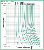
Despite this potential for shock, a TPS can be designed and utilized in a way that will control this risk and make it negligible. First off, we can think of what kinds of faults can occur. An accidental shorting from a live part of the TPS to ground would cause lots of current to flow, so fusing the input (mains) side of the TPS is very important. There is some inrush into caps C1, C2 at turn on, but a fast-blow fuse rated for 1A should have sufficient headroom to remain intact for the first cycle or two until the current settles down. Other types of faults will also lead to this fuse blowing, but downstream components might experience much higher voltage than usual and may fail before the fuse blows. These components (e.g. in the load) should be chosen so that in the case of a fault that delivers AC mains voltage to it, this voltage cannot be passed on to parts of the equipment that can be touched (like casework) or that lead out of the equipment (e.g. chassis connectors, etc). Even an panel-mounted LED indicator should NOT be powered by a TPS if the LED is not isolated from the chassis, e.g. by a plastic light pipe or similar arrangement.
The most common use for a TPS in audio equipment is to power relays and other turn-on type systems (soft-start, etc.). In that case, the TPS and load (relays) can be kept sufficiently isolated from other systems to comprise a relatively safe system. An electrically isolating subenclosure for the TPS is good practice, and keeps all exposed metal of the TPS protected and away from foreign objects (e.g. paper clip) that might enter the main enclosure thru ventilation holes.
In the meantime, I thought I would talk a little bit more about the transformerless power supply (TPS). If we think about it in a simplistic way, a TPS is an AC source with a current limiting element that is connected to a bridge rectifier and then smoothing caps. The output is then (must be) connected to a load for the TPS to function properly. If you consider the bridge diodes to be switches that open when the "upstream" voltage is higher than the "downstream" voltage (and closed otherwise), it is easy to see why the TPS is very dangerous in terms of shock hazard. Whenever the diodes are conducting (e.g. like an open switch) you have the AC mains connected across the current limiting element (C1/C2) and then the load. Essentially the TPS is a fancy voltage divider. That's it in a nutshell. What you have is a direct connection of the load to your household wiring, with only a couple of components in there limiting the total current flow during the conduction cycle of the diodes. This is why no part of the circuit wiring, including the load, should be accessible if you have any regard whatsoever for safety.
Despite this potential for shock, a TPS can be designed and utilized in a way that will control this risk and make it negligible. First off, we can think of what kinds of faults can occur. An accidental shorting from a live part of the TPS to ground would cause lots of current to flow, so fusing the input (mains) side of the TPS is very important. There is some inrush into caps C1, C2 at turn on, but a fast-blow fuse rated for 1A should have sufficient headroom to remain intact for the first cycle or two until the current settles down. Other types of faults will also lead to this fuse blowing, but downstream components might experience much higher voltage than usual and may fail before the fuse blows. These components (e.g. in the load) should be chosen so that in the case of a fault that delivers AC mains voltage to it, this voltage cannot be passed on to parts of the equipment that can be touched (like casework) or that lead out of the equipment (e.g. chassis connectors, etc). Even an panel-mounted LED indicator should NOT be powered by a TPS if the LED is not isolated from the chassis, e.g. by a plastic light pipe or similar arrangement.
The most common use for a TPS in audio equipment is to power relays and other turn-on type systems (soft-start, etc.). In that case, the TPS and load (relays) can be kept sufficiently isolated from other systems to comprise a relatively safe system. An electrically isolating subenclosure for the TPS is good practice, and keeps all exposed metal of the TPS protected and away from foreign objects (e.g. paper clip) that might enter the main enclosure thru ventilation holes.
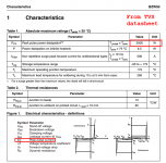
So buy one of those 5000 watt Transient Voltage Suppressor diodes (example) and put it in position Z1. If a fault occurs which would have put high voltage on the output, mister TVS turns on and clamps this to a safe level. Meanwhile, current goes to Ten GerBillion amps and the fuse blows extremely quickly.
So buy one of those 5000 watt Transient Voltage Suppressor diodes (example) and put it in position Z1. If a fault occurs which would have put high voltage on the output, mister TVS turns on and clamps this to a safe level. Meanwhile, current goes to Ten GerBillion amps and the fuse blows extremely quickly.
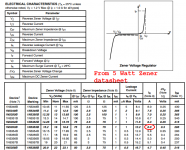
Won't 1A zener Z1 already do this (short excess voltage back to the AC return via the bridge)? I envision the zener breakdown voltage to be the same as the desired output voltage (between V+ and GND). Sure, it will blow up in short order, but I think the 1A fuse would go first since the same current would flow thru each of them.
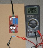
I finally had all the parts in hand to test version 1 of the PS board. I populated it as a TPS after doing some sims to determine the correct component values. During my brief test it worked like a charm. With a resistor as a dummy load it maintains approximately the desired 12Vdc output (floating). See attached.
The only issue I noticed is that the 100R, 3W inrush limiting resistor heats up relatively quickly. It's not so hot that I can't touch it, but it might be 60C after only a minute of use, which is probably too hot. I don't want to reduce the resistance of this part or the inrush will increase and I may replace it with a 5W part in the next version. Otherwise everything seems to have worked as advertised. Next test is to replace the dummy load with a couple of my relay boards and see how that goes.
The only issue I noticed is that the 100R, 3W inrush limiting resistor heats up relatively quickly. It's not so hot that I can't touch it, but it might be 60C after only a minute of use, which is probably too hot. I don't want to reduce the resistance of this part or the inrush will increase and I may replace it with a 5W part in the next version. Otherwise everything seems to have worked as advertised. Next test is to replace the dummy load with a couple of my relay boards and see how that goes.
Attachments
Replace it with three 3W resistors in series, each resistor 33 ohms? These 3W resistors are smallish: 4mm wide by 9mm long. Mount them vertically and they're still not as tall as electrolytic caps C3 and C4. You can insulate the exposed lead with a piece of insulation cut from a 22AWG piece of hookup wire, or you can just surround the entire vertical resistor with a piece of heatshrink tubing, and shrink it to form an insulated monolith. Looks like the PCB layout in post #1 has oodles of room to scoot R1 and R2 around, making room for the new parts. Sliding the fuse north would be helpful too.
If you can hold your finger on it for 10 sec or longer, it isn't too hot.
-Chris
I think I have one of those infared non-contact thermometer guns. I can fire it up and measure once a minute until the temp stabilizes without having to guesstimate. The resistor is a 3W ceramic (encapsulated) radial type, so getting hot is probably no problem for it. Maybe I could lay out the board using two of that type to spread the heat across more parts. I prefer them in this application because the leads are not exposed when the part is installed.
The resistor is not too hot.
It may be too hot for the board or nearby components. I've seen many hot resistors that were resisting fine but had cooked caps, Zeners, and even solder joints.
Is that it between the soft plastic screw-block and the damp electrolytic caps? IMHO, in Mk II you should move it out and away from such parts.
The resistor is not too hot.
It may be too hot for the board or nearby components. I've seen many hot resistors that were resisting fine but had cooked caps, Zeners, and even solder joints.
Is that it between the soft plastic screw-block and the damp electrolytic caps? IMHO, in Mk II you should move it out and away from such parts.
It's the white colored rectangular thing to the left of the two blue X2 caps in the pic. There is probably 4-5mm in between them (there is a 1/4W carbon resistor in between that you can't clearly make out). I don't think it is too close to other components. I still need to measure how hot it gets to know for sure. Maybe it's fine and I am just overreacting.
I can't really move it over to the board edge. There is another trace carrying 120VAC there under the board and I want to keep the necessary spacing for that voltage (and then some).
But it's at mains voltage.If you can hold your finger on it for 10 sec or longer, it isn't too hot.
-Chris
One has to unplug and ensure the voltage has dissipated to a safe level before one can touch the resistor to find how hot it is now.
A temperature indicating paint might work well enough.
I doubt one of the IR temperature sensing guns would work on a component as small as a resistor.
This is the type of discussion that was barred under the old rules.
Hi Andrew,
But, it isn't under current (sic) rules.
An isolation transformer would be a more likely item to be found in a hobbyist's bench than temperature indicating paint. Plus, resistors are insulated very well and I can't see anyone motivated to touch what would clearly be an even hotter surface than the body of the resistor.
Hi PRR,
Good point about proximity to other heat sensitive components. I totally agree with you on this. I guess the best thing to do would be to drill holes in the PCB along each side of the resistor. That would create an "air wall" that would guide all but the convective heat away from the other parts. It will also drop the temperature of the resistor. Mounting it up off the board is also a normal practice. Having another look at the board, it seems to be laid out much like the bulk of similar boards I've seen.
I'd say to add some ventilation holes and you're good to go.
-Chris
But it's at mains voltage.
One has to unplug and ensure the voltage has dissipated to a safe level before one can touch the resistor to find how hot it is now.
A temperature indicating paint might work well enough.
I doubt one of the IR temperature sensing guns would work on a component as small as a resistor.
This is the type of discussion that was barred under the old rules.
I am definitely NOT going to touch ANYTHING on the PCB while the circuit is powered (connected to AC mains). That would be risky. I previously unplugged it before testing the power resistor temp. There is a bleed resistor across the X2 caps that discharge them over a couple of secs, so once disconnected from AC power I can touch parts after, say, 10 seconds without risk of shock.
In any case, thanks for pointing that out.
Get a Variac. It'll let you perform soooooooooft start on prototype amps without having to stuff and solder and interconnect a soft start board first. Variacs also include a mains switch so you can cut the power and then touch your finger to a possibly very warm component, less than 1/3 second later. And the decent ones include an ammeter which you can use instead of a dim bulb tester to gently test for shorts, backwards diodes, wrong-phase windings, and other catastrophic errors: dial it up from 0VAC to 10VAC over the course of ten seconds, while watching the ammeter. If it shows > 0.1 amperes, stop!
Get a Variac. It'll let you perform soooooooooft start on prototype amps without having to stuff and solder and interconnect a soft start board first. Variacs also include a mains switch so you can cut the power and then touch your finger to a possibly very warm component, less than 1/3 second later. And the decent ones include an ammeter which you can use instead of a dim bulb tester to gently test for shorts, backwards diodes, wrong-phase windings, and other catastrophic errors: dial it up from 0VAC to 10VAC over the course of ten seconds, while watching the ammeter. If it shows > 0.1 amperes, stop!
Um, sure I have a Variac - best used for slow turn on of mains. But you seem to have forgetten one important point: If my TPS circuit happens to be disconnected from VA mains at peak AC voltage this will remain in its capacitors. Cutting the AC power does NOT do anything to protect you from the risk of SHOCK from the stored voltage! That is exactly what can happen here. There must be a way to bleed off any stored charge from the X2 caps, which I do with a 1M resistor across them. It takes several seconds for enough charge to drain for the voltage to fall to harmless levels.
I found my infared thermometer and did a measurement of the resistor temp. I had to position the unit only a few inches away so the spot would be small enough, and carefully aim but I could get pretty reliable readings this way. After a few (e.g. 5) minutes powered up the resistor temp leveled off around 90C. That is too hot IMO.
So, how to reduce this heat? I could split the heat generation across two resistors, but this would not really drop the temp all that much if combined they are the same resistance. I could halve the resistance to reduce the power generated by half. This would reduce the power that is turned heat but would also increase the turn on surge. I could exchange the resistor with an NTC thermistor of appropriate value. This would keep the inrush under control and would drop in resistance as it heated up, eventually reaching a (hopefully) lower temp overall. I will probably try that approach before deciding on how to proceed with the rev 2 board design and layout.
The other option is to realize that these are the kinds of issues that restrict the power capability of the TPS type of power supply to under 100mW. If I reduce the total capacitance in the X2 dropping capacitors their reactance will increase and the fixed power resistor will represent less of the total reactance+resistance in series with the AC mains. As a result the resistor would have less voltage drop and therefore less power loss and heat generation.
Last edited:
UPDATE: I received a 10-pack of 100R NTC thermistors the other day and I thought I would give them a try. This is a much better solution for inrush compared to the 3W power resistor.
I picked these 5mm diameter parts up on Ebay here:
10 x 100 OHM NTC Thermistor 5mm. - USA Seller - Free Shipping | eBay
It was just a matter of unsoldering the bulky resistor and soldering the smaller NTC thermistor in its place. I again used the same 150R dummy load for testing purposes. I plugged in the board and waited for magic smoke to emerge, but there was none. After a few minutes I unplugged the board and, after waiting a few seconds for the charge to dissipate, I did a finger test of the thermistor. It was only luke warm. I plugged the unit back in after 45 seconds or so and the fuse did not blow, so I imagine there was already some recovery in the resistance by then. It seems that it is doing its job of inrush suppression while not generating so much heat as the power resistor did, as described in the last post. Seems like the thermistor is the way to go.
Last edited:
- Status
- This old topic is closed. If you want to reopen this topic, contact a moderator using the "Report Post" button.
- Home
- Amplifiers
- Power Supplies
- linear or transformerless power supply board with snubber hat