Can an analog scope also work?
I'm re-posing this question:
Can one use the QuasiModo board with an analog scope?
Ah, OK, I should have figured that out seeing those images in the thread!Please see posts #405, #473, and #1127 in the Quasimodo thread. I tried linking to them here, but for some reason, all three links (which were different, I double checked!) took me to Quasimodo post #1 instead.
What you have created in the QM jig seems like some nice functionality. Please excuse my naiveté, but I am not sure why one could not just make these measurements on the PS itself, while it is "on"... it seems plausible that one could add the CRC components, choosing your suggested starting values of 10nF and >=150nF, and then trim the 1k pot while looking at a scope of the PS while it is powered on, into a low or no load so that conduction angles are low. I have a sneaky suspicion this doesn't' work for some reason, but am not sure what that is exactly. Is this because the measurement must be done with the transformer primary shorted?

I sort of know what is going on, but only to a shallow level - not enough to know what I don't know (and possibly be a danger to myself)! I would like to learn more about these finer details of PS design that don't seem to be widely disseminated. Learning how to use a scope correctly/safely is also on my to-do list... maybe the jig is a good opportunity to jump into this.
Last edited:
You are asking: What would happen if I did X??
The correct answer is: do X and find out.
--------------------------------------------------
Suppose you used some the very best diodes, diodes whose ranking was near the top in the Linear Audio article. The ones that stimulated very very little transformer ringing.
Further suppose your transformer's secondary leakage inductance is very low. In my experience, transformer secondary leakage inductance can vary over a range of more than 100 to 1. Suppose you happen to have a transformer near the bottom end of the range.
Now you've got a low dI/dt (thanks to the use of an excellent diode) at turn-off, and a low leakage inductance L. Thus the voltage spike L*dI/dt at diode turn-off is very small, and you might not be able to trigger your scope on it. Certainly I've seen plenty of real-life power supplies where I couldn't trigger any of my scopes. (That's another reason why Quasimodo the Bellringer was born: no more of this feeble stimulus nonsense, let's make a jig that will deliver a Big Ol' Bohunker WHACK!, big enough to make ANY transformer ring with a dozen volts of peak to peak oscillation).
However, there does exist a (repulsive) workaround, if you're stubbornly determined not to use a Bellringer jig at all: Remove the excellent diodes and temporarily install some terrible diodes. Pick diodes near the bottom of the LA rankings. You'll get more ringing, and now you'll have an easier time of triggering your scope on the ringing waveform. Assuming that you can now see the ringing, tune the snubber. When you've found the optimum value of snubbing resistance, remove the terrible diodes and reinstall the excellent diodes. An extra one or two hours of pleasant DIY hobby time, right?
For me, personally, the answer was: wrong. I would rather spend ten minutes doing a Quasimodo test, than 60 minutes swapping diodes. Plus, the trimmer potentiometer is easy to adjust on the Quasimodo test jig; perhaps not so easy to adjust when it's buried inside the guts of the actual power supply, within the chassis of your audio equipment. And I find it just a little bit safer to perform a Quasimodo test using a 9V battery, than a live-equipment test using the (lethal) AC mains voltages. All other things being equal.
rectification, Can anybody gives advice on choosing two types of rectification? case one, a Sanken 50A, 400or 600V bridge with heat sink, or case two, four of the schottky diode that rate of 150V, 120A rating each with heat sinks also. I am preparing the power supply for my 100 w /per channel power amp, 36VAC secondary. Any benefit to use the much more expensive shottky diodes on the sound quality? less ripples? low noise? safe for coming spikes?
Charlie, you haven't identified all the basic power supply values that would be used to determine a suitable diode, or attempted to identify the likely surge and continuous current requirements. As well as a 62-0-62Vac secondary winding on the power transformer, a DC loading of 500W, and the filter capacitance, you need to define power transformer winding resistances.
Many people have used the design tables prepared by Schade back in 1943, and nowadays simple applications like PSUD2 can estimate diode turn-on surge and continuous peak and average current levels. You will need to measure power transformer windings resistances yourself. From there, many diode datasheets can indicate the power dissipation in each diode (using the simulated peak and average current levels). You need to set yourself a happy maximum junction temperature, and then from your amp's ambient temperature environment and the way you want to heatsink the diode (free air or aided by a heatink), you can see if the diode's junction temp will at least be below your happy Tj max.
Or you can wing it, or look at what diodes are used in equivalent amplifiers, or get some suggestions from this thread, or just buy some diodes and see if they go poof.
With at least that basic check, then you can progress on to different types of diodes as suggested in this thread - some diodes have higher dissipation for the same operating current levels (typical of fast-recovery types, and typical of some diodes with a higher PIV in the same model range) - some diodes allow easier heatsinking (so could be operated at lower junction temperature) - some diodes have a higher surge current rating (to withstand turn-on) - some diodes with higher current rating have higher Qrr (making reverse recovery more of a concern) - some diodes have higher junction capacitance (making it easier for noise to pass through them).
and very fast switching does not help the ringing either
LINK
Abstract: Power transformer secondary ringing was measured with 48 different semiconductor diodes; ringing amplitude was 10-20X lower with the best diodes than with the worst. They all rang, including Schottkys and HEXFREDs. { but some rang a lot less than others }
... The Soft Recovery diode with the highest datasheet "softness ratio" (tb/ta), was among the eight double gold medalists.
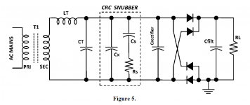
... It was also found that CRC snubbers eliminate ringing completely, even with the poorest diodes.
Abstract: Power transformer secondary ringing was measured with 48 different semiconductor diodes; ringing amplitude was 10-20X lower with the best diodes than with the worst. They all rang, including Schottkys and HEXFREDs. { but some rang a lot less than others }
... The Soft Recovery diode with the highest datasheet "softness ratio" (tb/ta), was among the eight double gold medalists.
... It was also found that CRC snubbers eliminate ringing completely, even with the poorest diodes.
How to build a CRC snubbers? is there a kit? or we could build on a bread board or universal board. Following your thread says, I have ordered Sanken bridge rectifier 25A/600V, instead of 150V, 120A Schottky diodes (x). So I am exicted to install this CRC.
secondary, 36VAC for 100W amp.
secondary, 36VAC for 100W amp.
build a quasimo do test jig
By the way, I have ordered ordinary bridges for my power-amp, instead of purchase expensive power schottky diodes because that this thread tell us all the diodes ring, no matter it is fast diode, soft recovery or even schottky, or HEX.
Yes thanks to everyone, specially Mr. Johnson. Where can we buy this quasi test jig? It seems that the parameter Rs is quite individual. No universal solutions unfortunately, each transformer, add up different secondary voltage set up need to be tested. So we need a power-supply, a signal generator, and a jig to determine the ultimate Rs value free from the ringing? Forgot, there is a scope to read the osc also. Sign generator should be set at 120 hz for 60hz AC, What about the voltage supply value? match the secondary output, 36VDC in my case?A picture tell a thousand words. Now I know exactly what you were talking about.
-Chris
By the way, I have ordered ordinary bridges for my power-amp, instead of purchase expensive power schottky diodes because that this thread tell us all the diodes ring, no matter it is fast diode, soft recovery or even schottky, or HEX.
you don't need a signal generator.Yes thanks to everyone, specially Mr. Johnson. Where can we buy this quasi test jig? It seems that the parameter Rs is quite individual. No universal solutions unfortunately, each transformer, add up different secondary voltage set up need to be tested. So we need a power-supply, a signal generator, and a jig to determine the ultimate Rs value ...................
The fast switching current circuit is inside the quasimodo jig.
You do need an oscilloscope.
you don't need a signal generator.
The fast switching current circuit is inside the quasimodo jig....
Further to Andrew's points, the switching circuit doesn't need to be at 100Hz or 120Hz; the bell's ringing frequency and dampening values are independent of how often Quasimodo smacks the bell.
Same for voltage; ringing frequency/dampening values are independent of how hard Quasimodo smacks it (as long as he smacks it hard enough to ring).
Mark's document is well worth reading; it covers these points and others of interest.
Cheers,
Jeff.
- Status
- This old topic is closed. If you want to reopen this topic, contact a moderator using the "Report Post" button.
- Home
- Amplifiers
- Power Supplies
- pros and cons of monolithic bridge rectifiers for power amp PS