One last try before I give up.
I would flip V2 around and call it '12V' instead of '-12V'. Same thing, but more intuitive. For me
Jan
Do you realise that with two isolated supplies (v1 & v2) you can use two +ve regs, or use two -ve regs, or as here one +ve and one -ve?
One often finds that with two polarity complementary circuits that one polarity version performs better than the other.
In this case you would be better adopting two of the better circuit and series connecting them.
One often finds that with two polarity complementary circuits that one polarity version performs better than the other.
In this case you would be better adopting two of the better circuit and series connecting them.
Last edited:
Andrew, I was under the impression that there need to be two seperate supplies to create a bipolar supply. I was planning to use dual secondary ( 9-0-9)V transformer with two bridge rectifiers to do this. If I can just use either 0-9 V or a single bridge with 18V and make a bipolar supply +/-6V it will be better in terms of cost. Is it possible?
Do you realise that with two isolated supplies (v1 & v2) you can use two +ve regs, or use two -ve regs, or as here one +ve and one -ve?
One often finds that with two polarity complementary circuits that one polarity version performs better than the other.
In this case you would be better adopting two of the better circuit and series connecting them.
Good job to confuse a learner who had just about figured it out. We know you know it all, no need to demonstrate it again.
Jan
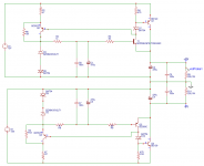
Phew! this time, everything looks about right -don't touch anything now-, at a later stage, the 1Meg resistors could be replaced with 10, or even 22Meg, to scrape half a dB of rejection, and D7 D10 can be ordinary 1N4148, they will perform as well and may ease the startupThanks Elvee! How does it look now?
For most transistors, but especially T2 Q5, a lower β will mean a lower Early effect, and a better hum rejection: use preferentially B types, and even A types if you can find themIs there any advantage/issue with using B vs C devices?
Why not increase R2 & R8 (post 87) if your number-one priority is preventing zener diode noise from reaching the output?
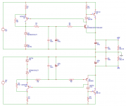
Or, if instead your number-one priority is preventing unwanted AC garbage on the +12V input, from reaching the output ... why not consume some of that (12V - 6V) = 6 volts of headroom by using an LDO preregulator? It'll give you an additional 75dB of input rejection.
Or, if instead your number-one priority is preventing unwanted AC garbage on the +12V input, from reaching the output ... why not consume some of that (12V - 6V) = 6 volts of headroom by using an LDO preregulator? It'll give you an additional 75dB of input rejection.
I was planning to use dual secondary ( 9-0-9)V transformer with two bridge rectifiers to do this. If I can just use either 0-9 V or a single bridge with 18V and make a bipolar supply +/-6V it will be better in terms of cost. Is it possible?
9-0-9 Vac, i.e. a center tapped secondary winding, won't work with two rectifier bridges. Simply use one. The center tap will be the return for both the negative in- and output of the positive andfor the positive one for the negative half of your arrangement. Sounds complicated, but isn't
.Best regards!
Sorry ,it is not a center tap ,it is a transformer with 9-0,0-9 seconadries.
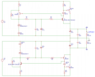
Yes it was a challenge.Thank you all. Elvee, made all recommended changes.
There is more.Please see the complete schematic.To reduce the size going with CRC instead of CLC.
Mark give me an example of LDO pre regulator,google not returning much results.
Yes it was a challenge.Thank you all. Elvee, made all recommended changes.
There is more.Please see the complete schematic.To reduce the size going with CRC instead of CLC.
Mark give me an example of LDO pre regulator,google not returning much results.
Attachments
See post #43 in this thread, especially its attachments.
LDO = Low Drop Out
An LDO regulator works fine when the difference between Vout and Vin is small. The one in post #43 is spec'd to work great for Vout as high as (Vin - 600 millivolts).
So ... you could put it upstream of your post #94 circuit. Now your circuit gets 11.4V input instead of 12V; whoop de doo. Your input rejection increases by 75 dB (5600X) which you may find desirable.
PREcede your circuit with a REGULATOR ... voila, PRE-REGULATOR.
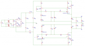
It looks fine now. Note that C7 C8 and probably C5 C6 are completely dispensable: at best, they will do nothing, and at worst they will introduce unwanted resonances, albeit at frequencies that probably don't matter too much.Sorry ,it is not a center tap ,it is a transformer with 9-0,0-9 seconadries.
Yes it was a challenge.Thank you all. Elvee, made all recommended changes.
There is more.Please see the complete schematic.
Have a look at the impedance curves of parallel combinations here, you will understand why:
Paper-in-Oil Capacitors
For C5 C6, if they are at the POL, they might be justified and do some good.
- Status
- This old topic is closed. If you want to reopen this topic, contact a moderator using the "Report Post" button.
- Home
- Amplifiers
- Power Supplies
- Zener+Voltage follower