It depends on applications, but high level is the right approach for your case. A transition design. The last module I designed with hand written 8 bit assembler MCU code in it has been selling for 5 years since design was completed, as part of several products, and is still a winner in terms of performance. A reference design.
Looking at the list of pins, I suppose these are families of pins that can expand into one or more. Looking good.
Looking at the list of pins, I suppose these are families of pins that can expand into one or more. Looking good.
It depends on applications, but high level is the right approach for your case. A transition design. The last module I designed with hand written 8 bit assembler MCU code in it has been selling for 5 years since design was completed, as part of several products, and is still a winner in terms of performance. A reference design.
Looking at the list of pins, I suppose these are families of pins that can expand into one or more. Looking good.
I know my car's ECU is running assembler code probably a Motorola 6800 MCU, engineers who design machines on this level are the Leonardo Da Vinci of electronics, everything from an abstraction.

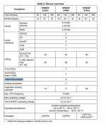
$2 part. Good old LM35. comes as a 3-Pin TO-220 easy to mount as well!
Texas Instruments LM35DT/NOPB Temperature Sensor, 0 → +100 °C, 3-Pin TO-220
http://za.rs-online.com/web/p/products/5359458/
I would have considered a DS1820B but this part is overkill and not easy to mount as I need to seat this flush on the heartsink, another application may benefit from this "network" capability, 127 devices on a one wire bus with all kinds of goodies amazing (not for this application) !!!
If it is for controlling overheating, what about 10% SMD NTCs in PCB and a dot of silicone to couple them to heatsink? Not many sense points needed as there are no independent channels or PSU like in an amplifier. You will have to cook the data from the NTC with code in the MCU, but not as difficult as making a temperature limiter for an amplifier, where poles and zeros at frequencies below 1Hz have to be introduced to compensate thermal dynamics in order to close a NFB loop around a NTC glued to somewhere with silicone. The purpose of using MCU is to move to the coding domain some complexity of the analog domain. Cost of SMD 10% NTC around $0.1...
are you considering the tms320F2807 ? cheap because used in many products. not a true DSP (MAC operation is actually an ACM, need to stuff another AC to finalize the mac operation, but it can be handy if you have something already residing in the accumulator). far from a straightforward motorola product like the 56k series.. it was the beginning of the new trend of conceiling chip errors in the compiler, or for example calling it "sensor controller studio" (TI) software environment.
If it is for controlling overheating, what about 10% SMD NTCs in PCB and a dot of silicone to couple them to heatsink? Not many sense points needed as there are no independent channels or PSU like in an amplifier. You will have to cook the data from the NTC with code in the MCU, but not as difficult as making a temperature limiter for an amplifier, where poles and zeros at frequencies below 1Hz have to be introduced to compensate thermal dynamics in order to close a NFB loop around a NTC glued to somewhere with silicone. The purpose of using MCU is to move to the coding domain some complexity of the analog domain. Cost of SMD 10% NTC around $0.1...
Your idea is even better!
, I'm just concerned about the mechanical mounting/shock reliability using silicon, but at $0.1 its a no brainier. I have a few that I salvaged from an old 90's car amplifier. funny this technique is still prevalent today. Car amplifier's have a small metal mounting tab to seat the "disk" shaped NTC's to the heat-sink so silicon/adhesive can be avoided.
10Pcs Temperature Sensor Resistor Thermistor NTC-MF52-103/3435 10K 3435 | eBay
http://www.cantherm.com/wp-content/uploads/2017/05/cantherm_mf52_1.pdf
Last edited:
The factory-made DC Electronic Load that I bought, has two channels. I find this very handy for characterizing dual-rail power supplies such as the ones used in audio power amplifiers.
For example a ±60V @ 2A supply can be tested on a single channel electronic load, as long as that load can accept 120V @ 2A. Whereas a dual channel load only needs 60V @ 2A per channel. Less max-Voltage required.
In constant current mode the channels can be connected in parallel, of course. And you don't even need to run the same current per channel, so you can leisurely dial up the current on channel A, then slowly and deliberately dial up the current on Channel B. It's convenient.
Food for thought: Since the subject of SMD parts has come up you should read the post "Distortion in Resistors is real" and post #41 SMD parts.
Since most of the loads may be DC, low frequency's or pulsed waveform's their may be some drift due to heating of the current sampling resistors.
In my case 25ppm parts were a problem.
Duke
Since most of the loads may be DC, low frequency's or pulsed waveform's their may be some drift due to heating of the current sampling resistors.
In my case 25ppm parts were a problem.
Duke
are you considering the tms320F2807 ? cheap because used in many products. not a true DSP (MAC operation is actually an ACM, need to stuff another AC to finalize the mac operation, but it can be handy if you have something already residing in the accumulator). far from a straightforward motorola product like the 56k series.. it was the beginning of the new trend of conceiling chip errors in the compiler, or for example calling it "sensor controller studio" (TI) software environment.
TMS320F2807 I have this part, x10 actually I won last year, but I wont be using this part, I want to use it for a more specialized application like my DIY MPPT project I want to develop next year sometime, this eload project calls for simplicity, a 16-bit MCU is more than enough. DSP sampling rate for this application will way below 3KHz, however place a DSP application in the audio domain and the CPU cycles will add up very quickly making these MCU's chips unsuitable.. maybe for a sub-woofer application/single channel application for a MIC.
Food for thought: Since the subject of SMD parts has come up you should read the post "Distortion in Resistors is real" and post #41 SMD parts.
Since most of the loads may be DC, low frequency's or pulsed waveform's their may be some drift due to heating of the current sampling resistors.
In my case 25ppm parts were a problem.
Duke
Each stage inherently will have noise and suffer from some sort of thermal drift, but software can trim this even with age, I'm concerned about the noise floor..I'm trying to avoid large amplifier gain stages, like x1000 amplifier gain blocks and large input divider networks like 100, example: using a R1/R2 divider ratio of 100, 2.2Meg and a 22K, for an input of 1mV will output about 10uV, using x1000 amplifier the output is 1mV, however.. we are amplifying a signal and its noise. Some measuring instruments use guard traces around the inputs of op-amplifiers/ADC's to avoid stray interference.. I'm able to disturb an amplifier with x1000 gain just by hovering my hands over its inputs.
I'm trying to work out out a better resistor scaling network arrangement at the moment, its like designing a cheap digital multi-meter with auto scaling done in software...
Last edited:
Ok, I'll try help redesign the mosfet and its sensing. About the MCU I'm not good at it, usually I have my friend did it. and looks like 8bit and 16bit mcu is no more supported by him. he said that today ARM based MCU is cheaper at the end, easier, and quicker to hand the project because its also very good with RTOS, and M4 can also run some linux app.
I did some quick search and found stm32f373 was cheap ($5@digikey and $3+@aliexpress), it has precise 12bit ADC, +-0.7LSB of INL. and 3x16bit SDADC (sdadc isn't good for dc but it may still worth).
You can choose which best MCU for $6 margin, I can order it and start with the mosfets. I need some specific information about its limitation and operating range. Will message you about it later.
Ok, I'll try help redesign the mosfet and its sensing. About the MCU I'm not good at it, usually I have my friend did it. and looks like 8bit and 16bit mcu is no more supported by him. he said that today ARM based MCU is cheaper at the end, easier, and quicker to hand the project because its also very good with RTOS, and M4 can also run some linux app.
I did some quick search and found stm32f373 was cheap ($5@digikey and $3+@aliexpress), it has precise 12bit ADC, +-0.7LSB of INL. and 3x16bit SDADC (sdadc isn't good for dc but it may still worth).
You can choose which best MCU for $6 margin, I can order it and start with the mosfets. I need some specific information about its limitation and operating range. Will message you about it later.
http://docs-europe.electrocomponents.com/webdocs/14f4/0900766b814f4531.pdf
Perfect MCU choice! it even has a 12bit DAC, one less part to deal with. looks like the only external parts remaining is an external reference and spi flash memory to store the data logging, store settings and calibration data.
2.5Vref, 12bit ADC, 610uV per step, 4096 Quantization levels.
I will stay clear of any rtos for now, a state machine is simple enough. I have a licenced copy of keil V5 and a programmer header. I have a uncompleted STM32F4 DSP subwoofer project on my desk .
Attachments
Last edited:
which one you prefer? f3 or f4? f4 will be best for DSP, it has +-1.5LSB of INL. its decent 12bit ADC as well.
and it has more features.
I got both on order.
STM32F373V8T6, 32bit ARM Cortex M4 MCU, 72MHz, 256 kB Flash, 100-Pin LQFP
STM32F373R8T6, 32bit ARM Cortex M4 MCU, 72MHz, 64 kB Flash, 64-Pin LQFP
It turns out a 100PIN may still be attractive, user input buttons take alot of I/O and these devices are not badly priced, but I2C I/O expander is cheap as well.
As a reference this will come in handy.
How to filter the input of a high-side current sensing.
http://www.st.com/content/ccc/resou...df/jcr:content/translations/en.DM00086777.pdf
Precision improvement techniques
for the A/D converter of the STM8 microcontroller
http://www.st.com/content/ccc/resou...df/jcr:content/translations/en.CD00186359.pdf
UNDERSTANDING AND MINIMISING ADC CONVERSION
ERRORS
http://www.st.com/content/ccc/resou...df/jcr:content/translations/en.CD00004444.pdf
How to get the best ADC accuracy (here they talk about the white noise trick eva explained)
in STM32 microcontrollers
http://www.st.com/content/ccc/resou...df/jcr:content/translations/en.CD00211314.pdf
Last edited:
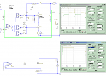
I did some changes to the mosfet and I need adjustment detail. load sharing between upper and lower mosfet and slope limit isn't implemented yet. will add later.
it has some advantage like short spike free from unstable source, and has quicker response.
it able to hold 100w by paralelling the main load with source resistor.
if you need ac 220v protection it required high voltage mosfet as the main load. but protecting from 220a isn't necessary.
the current sensing, since irfp250 max current in 30A it will safe to limit it at 15A. and the value of resistor can be adjusted to what you already have.
ok will order stm32f373 64pin. I ask my friend also and he recommend it.
any suggestion everyone is welcome.
it will be great project, isn't it?
Attachments
I did some changes to the mosfet and I need adjustment detail. load sharing between upper and lower mosfet and slope limit isn't implemented yet. will add later.
it has some advantage like short spike free from unstable source, and has quicker response.
it able to hold 100w by paralelling the main load with source resistor.
if you need ac 220v protection it required high voltage mosfet as the main load. but protecting from 220a isn't necessary.
the current sensing, since irfp250 max current in 30A it will safe to limit it at 15A. and the value of resistor can be adjusted to what you already have.
ok will order stm32f373 64pin. I ask my friend also and he recommend it.
any suggestion everyone is welcome.
it will be great project, isn't it?
Hi, good attempt thus far, I'm lagging behind these few days, I started work today and some of my parts only arrived today, but they did arrive
I'm settled with the STM32f373, lets keep this conversation for later and jump into the analog stuff for now.
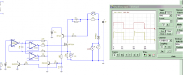
I see you have two servo amplifiers did you really need two ? or is the IRFP250 Qg placing to much demand on the outputs for a single servo amplifier. I have 20 pieces of 072 smd amplifiers I'm going to use for my prototype's servo stage.
Oh the question about shutdown, yes shutdown is important, it is used to turn off the load electronically (without using mechanical) relays, it will just mute the power mosfets, either from a user input (turn off/mute) or system shutdown command.
Last edited:
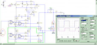
looks like its ok this way, 4 of irfp250n. and simulated @2v, they draw 50A+. slow but stable with a tl072 servo.
next will be current sensing, voltage sensing (easiest way is resistor divider but always draw minor current). after that a power converters. then PCB. I can take care of them.
can you re map the port? and choose how to sense the current and voltage? the source resistors can be ignored since it is used for servo feedback.
Attachments
- Status
- This old topic is closed. If you want to reopen this topic, contact a moderator using the "Report Post" button.
- Home
- Amplifiers
- Power Supplies
- DC Electronic Load