I'm building a DC Electronic load to test DC power supplies and batteries up to 100W.
Here is some specification.
- Maximum 30VDC
- Resolution 500uV
- Accuracy of 0.1%
- MCU protection, OV, OP, OC, OT
- Software slave controlled with data capturing logging
- PC remote control.
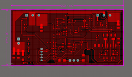
The schematic values hasn't been finalized but the building blocks are in place.
This is the analog board, the MCU I/O DAC/ADC board will follow.
Here is some specification.
- Maximum 30VDC
- Resolution 500uV
- Accuracy of 0.1%
- MCU protection, OV, OP, OC, OT
- Software slave controlled with data capturing logging
- PC remote control.
The schematic values hasn't been finalized but the building blocks are in place.
This is the analog board, the MCU I/O DAC/ADC board will follow.
Attachments
Last edited:
will you share everything? I can help you with the hardware since I don't have more time for the software.
Yes. I will release the firmware code and the gerber files.
I have to develop the prototype board first , I have a unused single side PCB that I will use for the prototype, after REV 0.1 that I will redo the board as a double sided board.
Where is the MCU? haha
Start by making a list of the amount of analog and digital I/O pins needed haha
To make this list, make another list of the MCU driven "gadgets" to implement, and develop each gadget.
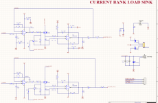
R3,R14 will burn when output is disabled. A second method is needed, like switching the positive rail of the op-amps.
C4,C11 can result in an oscillator.
Start by making a list of the amount of analog and digital I/O pins needed haha
To make this list, make another list of the MCU driven "gadgets" to implement, and develop each gadget.
R3,R14 will burn when output is disabled. A second method is needed, like switching the positive rail of the op-amps.
C4,C11 can result in an oscillator.
Where is the MCU? haha
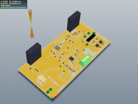
The board is modular, the above is the analog board. here is the PIC24 board with external ADC working.
Attachments
Start by making a list of the amount of analog and digital I/O pins needed haha
To make this list, make another list of the MCU driven "gadgets" to implement, and develop each gadget.
R3,R14 will burn when output is disabled. A second method is needed, like switching the positive rail of the op-amps.
C4,C11 can result in an oscillator.
I have made a list of I/O most of it reserved already. (if anything changes I do have enough I/O to work with) I keep a physical pin-out print of pin mappings with annotation..I'm mostly focusing on the DAC/analog drive circuit, the MCU part is not too difficult as I'm using a high level language like C and have the ADC, 2X16 LCD, Encoder and DAC sub systems functioning i.e correctly performing acquisition, displaying, reacting to encoder signals (user input) I have functioning xserial layer sending custom packets to the PC (via FTDI) with system register read/write configuration packets ect..
These are the core chips I used.
PIC24F256GB210
AD7708
DAC8831
ADR420
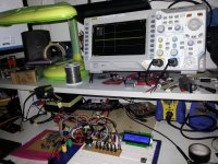
I am busy evaluating the MCU/DAC/ADC board (digital board) as its on a breadboard and subjected to lots of noise.
Thank you for the input.
What about the load working modes and bandwidth? I can suggest:
- Constant DC current mode.
- Pulsed DC current mode.
- DC resistor simulation mode.
- AC resistor simulation mode.
Good MCU starting point but no connection with output board design for the moment.
Thanks for the suggestion. For now I have constant current in mind with programmable pulsed commands.The bandwidth l have in mind is approx 30KHz. The challenge for now is to make sure the analog board works correctly and the SOA for the IRFP250 is not exceeded at 100W
AC load is different class, and with 30khz it will costly you may need super quick devices. better back to your DC electronic load as stated.
do you have arm mini pc? it running linux with its great stability and you can have decent user interface with it and touchscreen setting.
if not, your MCU is also good one.
do you have arm mini pc? it running linux with its great stability and you can have decent user interface with it and touchscreen setting.
if not, your MCU is also good one.
I can suggest:
- AC resistor simulation mode.
will you help with it? will be much appreciated.
what about its onchip 10bit sarADC come with the MCU?AD7708
DAC8831
ADR420
I am busy evaluating the MCU/DAC/ADC board (digital board) as its on a breadboard and subjected to lots of noise.
what about its onchip 10bit sarADC come with the MCU?
With this project I need precision and stability the on-board 10-bit MCU SAR ADC found on the PIC (and most MCU vendors for that matter) doesn't have the linearity of an external ADC for precision applications (even using oversampling tricks this cannot be reliably done) there are many ADC parameters to consider like Gain Error, INL (Integral Non-linearity), DNL (Differential Non-linearity)
2^10 = 2.441mV (per step) @ 1024 quantization levels with a 2.5V reference.
2^16 = 38.147uV (per step) I'm interested in measuring down to 500uV @ 65536 quantization levels a 2.5V reference.
Note i'm no expert, I'm learning alot about ADC precision applications and its a rather vast topic.
You can look at these ADC's, note I do know they not the cheapest, but they not grossly expensive. The real work involved using them is writing the low level drivers and studying the feature capabilities (so you can fully benefit what you paid for). I have a fully working driver for AD7708 using the internal calibration routes. however, I'm finding the AD7708 acquisition to be slow (typical delta sigma behavior), however... its not too much an issue as I'm not even sampling at 10Kps working purely with low dc sampling rates for now.
I might consider the AD7682, but this will only delay things as I spent many hours ready the datasheet, writing and testing a driver for it. perhaps with another project its definitely a faster part but speed is not critical and simplifies the project alot.
AD7708 $10.42 (Delta Sigma)
AD7682 $13.39 (SAR)
Last edited:
Note 10bit ADC is already better than 1% resistors in terms of gain error. Offset can be calibrated. Is non-linearity below 1% of concern?
Maybe?, but as you know critical ADC parameters is deliberately "missing" from the MCU datasheet, I don't see histogram plots, noise plots, temperature vs errors, what about missing codes?
Anyway, using an external ADC "may" reduce part, in an application.. In my case I have a PGA and buffer stage with lots of very useful configuration like self calibration coefficients and internal digital filter. The PGA is specially useful when I start with the auto raging and scaling on the different ranges.
I feel the MCU built in ADC is NOT up to the job, (maybe) but not without serious firmware (occupying flash) and upping the external part count, debugging / time (of which I have very little)
")
nthe data sheet says +-1LSB of INL, or 0.1% error, but if you prefer external so be with it, the most important is how you handle the current error? normally if you drive a mosfet there will be an error caused by load and component nonlinearity due to thermal canges and others, will you make the MCU also manage the error? or only external error amp with opamp?
Last edited:
nthe data sheet says +-1LSB of INL, or 0.1% error, but if you prefer external so be with it, the most important is how you handle the current error? normally if you drive a mosfet there will be an error caused by load and component nonlinearity due to thermal canges and others, will you make the MCU also manage the error? or only external error amp with opamp?
I'm planning on using low PPM type current sense resistors, the error amp is a AD8620 with external .1% resistors for the differential sense amplifier. also, I need to keep the fets maximum SOA parameters in mind for the x2 IRFP250 mosfets at 100W, 50W per device may be pushing it.?
This is another topic for another day but... the INA21x part could be used as a replacement, the resistors are on the die and laser trimmed at the factory) , as for temp delta changes, this is the job of the MCU firmware/calibration, I have looked into this topic (some time ago) and found using some sort of offset slope with calculated coefficients can work, but honestly at this stage its not important, neither is an interface to a single board computer all these spoils to divert attention from whats important.
Anyway, this is probably a premature conversation to have now lets focus on baby steps as alot of work remains in more critical areas like the analog domain circuity (Eva has already pointed out potential issues), I'm sure we can revisit this topic as its very interesting
Last edited:
Reactance, could you elaborate on what you mean by '0.1% accuracy', and what is making you choose that level?
Some may envisage 0.1% accuracy as the measurement of operating point volts and current, and so power measurement won't be that accurate, or that any variation over time doesn't matter as long as the datalogged measurement accuracy is 0.1%.
Or is it the accuracy of the operating point to a preset reference value (eg. set operating point current to be with 0.1% of 1.00A, but not worry about voltage as that may vary due to temp comp of power supply or mains voltage variation, or as a battery discharges). Or does it refer to the power parameter, as in a 0.1% accurate constant power discharge.
FWIW I can't envisage any battery related measurement needing to be with that much precision, unless you have some exotic clients, or are setting up for standards testing and are setting up say 10 loads for batch testing.
Do you have reference meters that are much better than 0.1% for the parameters you want to check?
I also don't see any comments on what '100W' means? Is that the load power rating at 30V, or does it extend down to some voltage, and then fall back?
What type of tests or measurements require an electronic load with 0.1% precision in current or resistance setting?
Is there a situation where a load sweep and interpolation is not enough for a measurement or test?
Of course you can argue that you want to experiment with higher precision chips and FPGA, and I would agree, but learning higher precision or FPGA is tightly associated with learning certain few applications where it is needed.
Last edited:
- Status
- This old topic is closed. If you want to reopen this topic, contact a moderator using the "Report Post" button.
- Home
- Amplifiers
- Power Supplies
- DC Electronic Load