
how this project is going?
My current project is finished. and next will be battery tester, with 800a discharger included.
 for the picture.
 My project is put on hold just for this coming week, I'm busy moving house and at the same time decided to setup a new work bench, its very frustrating working on a small work bench!, I will be back next week.
It makes a big difference to have proper design and prototyping workbenches, with enough shelves around for stuff so that the benches do not end up clogged. I'm in the process of renewing my design room, in my case separate from prototyping room. It's better to have both benches in same bigger room for working in embedded stuff if you can choose. Another interesting thing I discovered: photocatalytic paint for ceiling and walls, it breaks down all volatile organic compounds with the help of light, no smells result in easier focusing.
It makes a big difference to have proper design and prototyping workbenches, with enough shelves around for stuff so that the benches do not end up clogged. I'm in the process of renewing my design room, in my case separate from prototyping room. It's better to have both benches in same bigger room for working in embedded stuff if you can choose. Another interesting thing I discovered: photocatalytic paint for ceiling and walls, it breaks down all volatile organic compounds with the help of light, no smells result in easier focusing.
100% eva
rental/ownership of space has become very expensive (world wide) and R&D hobby electronics is putting massive strain on this area of recreation, I managed to get a room with a 6 meter square room which will have a workbench to design PCB'S, simulate and prototype of micro-controllers, also have my scope and PSU near me, also 2 PC's one for logging from my instruments to my PC'S. its been taking me 4 years to build up the resources given the fact im from South Africa and our economy is terrible.
.
they taken from the trees.
GL with your new place.
Okay I'm back in action, lots of stuff going on the pace will be slow.
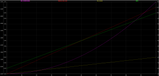
Attached are my simulations for my x2 0.12ohms (0.6 ohm) current shunts, each can deal with 10A @5Watts. I found a box of 25pc unused dale 3W LVR3 resistors
http://www.mouser.com/ds/2/427/lvr-239788.pdf
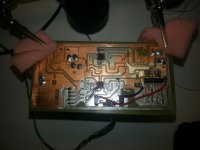
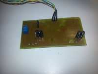
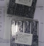
Also, see some assembly progress, thus far I found only one stupid PCB error I accidentally reserved the inputs to the regulators 317 and 337. luckily I used a psu with active current limiting set to 50mA. Both voltages are +/-1.5V with an effective 3V to interface with the MCU signal path.
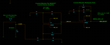
I am finalizing my final multiplier / divide network, a screen grab
Attached are my simulations for my x2 0.12ohms (0.6 ohm) current shunts, each can deal with 10A @5Watts. I found a box of 25pc unused dale 3W LVR3 resistors
http://www.mouser.com/ds/2/427/lvr-239788.pdf
Also, see some assembly progress, thus far I found only one stupid PCB error I accidentally reserved the inputs to the regulators 317 and 337. luckily I used a psu with active current limiting set to 50mA. Both voltages are +/-1.5V with an effective 3V to interface with the MCU signal path.
I am finalizing my final multiplier / divide network, a screen grab
Attachments
Last edited:
Do they work with +/-1.5v?
if not, you can make 3v signal from +/-15v opamp easily by resistors.
I'm back from my vacation and started to work. ordered some pcb at elecrow and now they have 5pcs option for only $5 for 5pcs 10x10cm pcb.
will upload if you need my layout. it is based on previous schematic of discharger.
if not, you can make 3v signal from +/-15v opamp easily by resistors.
I'm back from my vacation and started to work. ordered some pcb at elecrow and now they have 5pcs option for only $5 for 5pcs 10x10cm pcb.
will upload if you need my layout. it is based on previous schematic of discharger.
Interesting topic, I'm following ...
Just few useful information on this topic.
First one is regarding the "main dissipating device", I strongly recommend to use something more appropriate for this function like Thermal Track transistor with integrated (isolated) Si diode which can be used as very effective and fast temperature sensor which track exact temperature of silicon die.
That is a crucial requirement for suck kind of application, to keep temperature under TOTAL control.
I have used NJL3281D and I'm very satisfied how that thing works. I will not use anything else anymore except Thermal Track in any other application with similar requirements (large thermal dissipation), that device worth every penny, it is "indestructible" if properly controlled : )
https://www.onsemi.com/pub/Collateral/NJL3281D-D.PDF
GitHub - yu3ma/LM10_lin_psu: LM10 Linear Power Supply 0-50V 0-2A with temperature protection
Another interesting alternative is to use Power OP-AMP as main dissipating device, like LM3886, TDA7294 or similar, take an look on this topic regarding 4-quadrant power supply / load.
HQ Low noise 4-quadrant PSU with 2xLM3886
Another similar device for such purpose is LT1970A, very interesting IC!
http://cds.linear.com/docs/en/datasheet/1970afc.pdf
With such 4Q approach it is even possible to "return" loaded power back to mains if you have appropriate DC/DC converter, not to transform that into heat!
Regarding MCU, keep ARM on track, take also a look on STM32L4 and STM32F7 series, both are with DSP/FPU.
In general ST's A/D converters work very nice, those mentioned MCU series have extremely fast converters, more than 7MSPS, also including 12bit D/A.
For current sensing, watch this training series:
Getting Started with Current Sense Amplifiers | TI Training
They explain various stuff related to current sensing, big focus is on "error and accuracy".
For example, what "0.1% means", does it mean for "end of scale" or "beginning of scale" (two totally different parameters!), and so on, watch all series video, useful anyway.
Another interesting stuff by Mladen Veselic:
http://www.edn.com/design/test-and-...dles-difficult-loads--helps-characterize-PSUs
Last edited:
reactance, is there any difficulties there?
got an email, my pcb is shipped. so my friend start with the software, and I prepare ee25 transformer, heatsink, etc.
@ontoaba, apologies for the late reply!, I have been overloaded with day to day web operations at work (this time of the year clients wants to rap up loose ends making us work long lengthy hours)
I'm returning when, I take a break which is soon, my electronic load is going no where.
mine end up with stm32f407, 12bit ADC is decent, I got its lowest noise at around 290ks/s everything running in bckground, filtering, masking, timing, so far very nice MCU.
We also found this mcu is too powerful for simple task and planning to move the display from 20x4 to 800x480 lcd.
We also found this mcu is too powerful for simple task and planning to move the display from 20x4 to 800x480 lcd.
After a long while and long break I unpacked this project will start working on it again.
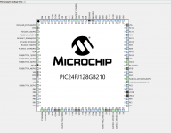
After some back and forth, I've finally decided to stick with using a PIC24FJ128GB210 for simple reasons, its basic, runs at 16MHz and has enough I/O to handle all the future I/O and most important, I wrote 50% of the firmware + driver code already!
- The external ADC will remain. I question the stability of a system relaying on an internal ADC with no INL or DNL specifications, I need all bits available with no missing codes.
- Using a stable voltage reference with the above, most of the R&D has been carried out, with the trade off of ~25$ cost.
At the moment I'm porting the code over to the XC16 compilers this weekend using the latest MPLABX.
Attachments
Last edited:
- Status
- This old topic is closed. If you want to reopen this topic, contact a moderator using the "Report Post" button.
- Home
- Amplifiers
- Power Supplies
- DC Electronic Load