I purchased 800XRE LLC power supply form China and while the product was of good quality a few things bother me.No service documentation or schematics, if it failed it had to be returned for repair. I know companies protect there products thinking this will prevent copying , reverse engineering.
Since a few of us like to repair the items we buy I find this annoying so I am starting a project for a LLC converter that can be scaled up to 1Kw. It is based on a thread by Lorylaci using the appnote an1160.
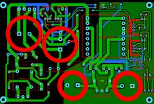
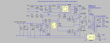
The schematic is attached, the first trial PCB layout has also being posted, there is no build yet but the transformers have been wound using EER 4220 and ETD 49 core sets. i will have pcb's in a couple of weeks.Most parts are TH but pcb is small. Some of the layout was from work done by Lorylaci, I posted a private message asking for permission but have not received a reply.
Chime in when you like
Since a few of us like to repair the items we buy I find this annoying so I am starting a project for a LLC converter that can be scaled up to 1Kw. It is based on a thread by Lorylaci using the appnote an1160.
The schematic is attached, the first trial PCB layout has also being posted, there is no build yet but the transformers have been wound using EER 4220 and ETD 49 core sets. i will have pcb's in a couple of weeks.Most parts are TH but pcb is small. Some of the layout was from work done by Lorylaci, I posted a private message asking for permission but have not received a reply.
Chime in when you like
Attachments
Last edited:
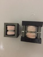
Transformers I wound for testing, large one ETD 49, small one EER 4220 AL for ETD about 4400 nH , EER about 5200 nH.
I subscribe what Eva wrote - you should learn to care for safety margins not only in the PCB-layout, but in the transformer as well. There are special two-chamber bobbins for LLC xformers on the market that meet safety requirements and permit usage of litz wire. You will find some examples of LLC-xformers readily wound inside the wuerth-catalogue. Do you plan any overload protection? Resonant currents and voltages will explode during short circuit conditions.
Last edited:
For making transformer isolation there are 4 options:
- Use triple insulated magnet wire for primary and/or secondary. No margins. 6mm distance is required from normal insulation magnet wire (if used) to the ends of triple insulated wire where insulation is removed for connections. Highest window fill ratio.
- Use 3mm margins at each side, both for primary and secondary sides, for lowest leakage inductance. Use 3 layers of normal transformer tape (mylar high temperature) as wide as the window area for separating primary side from secondary side. Use tape like this for making the margins: 3mm Adhesive Insulation Mylar tape High-Temp for Transformer Coil Wrap Yellow | eBay
- Use 6mm margin at one side for primary and 6mm margin at other side for secondary, for moderate leakage inductance. Use 3 layers of normal transformer tape as wide as the window area to separate primaries and secondaries. Use tape like this for making the margins (select 6mm): Adhesive Insulation Mylar tape High-Temp for Transformer Coil Wrap Yellow 66M | eBay
- Use split windings (what is shown in your pictures) with a 6mm tape margin in the center, or with a special coil former with split winding area, for high leakage inductance. You can prepare prototypes of such a coil former with pieces of plastic of coil former quality and epoxy as glue, be careful to make the gluing void-free. Otherwise the tape used is the same shown for previous options.
Note that such a powerful converter is going to generate a lot of stray field with split winding transformer, so a flux band is likely to be required. Split windings find more use in lower power converters. The alternative is using external inductor for proper series inductance.
Last edited:
Transformer & things
Eva, Thanks for your advise and as usual you are spot on, I might add that these transformers will need some adjusting to the resonant components that is why is I hand wound them. The way I adjust them is to monitor the current thru CR (resonant cap).
A question about current montioring, this control IC monitors the current thru the Mosfet but if not sufficient you can split the resonant cap.
I am attaching photo of a transformer wound by a house an high potted,and Iso certified.
Attachments

On another thread title IRS27951/27952
lorylaci
He made a Excel spreadsheet to help with the calculations.
http://www.diyaudio.com/forums/power-supplies/184487-irs27951-irs27952-2.html
lorylaci
He made a Excel spreadsheet to help with the calculations.
http://www.diyaudio.com/forums/power-supplies/184487-irs27951-irs27952-2.html
I have only seen split bobbin transformers used for far lower power outputs. At this power level the resulting leakage field will be unsatisfactorily high for audio. It will be like measuring with oscilloscope at any point in the amplifier and getting 50mV of PSU switching waveform.
Did your friend get it from China? Did your friend get the lowest cost one? The Chinese are usually not fair in their lowest price ranges. Just make the PCB 1cm wider and add a toroid inductor, micrometals -2 material recommended, as in class D output chokes. Wind the transformer for moderately low leakage and high window utilization, inner primary and outer secondaries. Litz wire could no longer be required. A decent audio SMPS in the 700W~800W range will be achieved that way. One of the rules about LLC is that an optimum transformer does not provide enough leakage inductance.
From my experience you can achieve about 400W of output power with 85kHz switching frequency and integrated magnetics core size ETD 39 and 2-chamber bobbin - the limit seems to be proximity effect of the litz wires. Following Evas proposal with a separete choke there should be more power available at that size. Personnally I prefer the integrated magnetics solution. There is no danger of saturating the stray inductance, primary-secondary capacitve coupling is minimal and all in all it looks more economic to me. Just my 2c.
Last edited:
Exactly! And no way to get decent reliability without OCP, OTP, OVP, UVP etc. 49mm ferrite is stupidly oversized for such power LLC (just add extra Lr) but 11A MOSFET's are too weak for 800W*2=1600W of a peak power, especially if no any OCP is implemented.Did your friend get it from China? Did your friend get the lowest cost one? The Chinese are usually not fair in their lowest price ranges. Just make the PCB 1cm wider and add a toroid inductor, micrometals -2 material recommended, as in class D output chokes. Wind the transformer for moderately low leakage and high window utilization, inner primary and outer secondaries. Litz wire could no longer be required. A decent audio SMPS in the 700W~800W range will be achieved that way. One of the rules about LLC is that an optimum transformer does not provide enough leakage inductance.
I agree that a smaller core set should be used, but I have these on hand , easier to wind, less copper and ETD39, 44 could be used. The proto will use the IRS27951 because I have a few on hand after I work out all the bugs I will use the NCP1395 Onsemi chip, another good choice is UC25600, TI chip. The Mosfets will be changed as necessary during testing along with other components.
Last edited:
chas1, can I suggest you take a look to MCU as LLC controller? It's cheap as a dirt, reliable and flexible ") Right now I testing frequency shuffling feature on stm8s003 chip as LLC controller, I gonna off the shuffling at powers higher than 1/8 of Pmax, to keep regulation quality well. So only for the EMC limits the shuffling is active, can you imagine if your chip candidates may do something like that? Another example - differently flashing LED which shows what kinda protection event is engaged?
Right now I testing frequency shuffling feature on stm8s003 chip as LLC controller, I gonna off the shuffling at powers higher than 1/8 of Pmax, to keep regulation quality well. So only for the EMC limits the shuffling is active, can you imagine if your chip candidates may do something like that? Another example - differently flashing LED which shows what kinda protection event is engaged?
Right now I testing frequency shuffling feature on stm8s003 chip as LLC controller, I gonna off the shuffling at powers higher than 1/8 of Pmax, to keep regulation quality well. So only for the EMC limits the shuffling is active, can you imagine if your chip candidates may do something like that? Another example - differently flashing LED which shows what kinda protection event is engaged?- Status
- This old topic is closed. If you want to reopen this topic, contact a moderator using the "Report Post" button.
- Home
- Amplifiers
- Power Supplies
- 700 - 800W LLC Converter