I have two identical torroid transformer laying around. Both have 117 Volt single primaries and two 20VAC 5 amp secondaries. I want to connect the two secondary windings in series on each transformer to get 40VAC 5 amps. Then connect the two transformer secondary windings out of phase to get 56-0-56. My question is: What is the total wattage for both transformers connected this way? I pretty sure I have 40VAC X 5amps = 200 watts for each transformer, but what happens to wattage when they are connected out of phase?
Attachments
be careful with wiring up multiple primaries and/or multiple secondaries.
I suggest you ALWAYS use a Mains Bulb Tester (MBT) to protect you and your equipment from damage.
Yes, you can series connect primaries. Each will see half the supply voltage.
Or you can connect the primaries in parallel (fuse each separately). Each sees the full supply voltage.
Similarly you can connect the secondaries in series or in parallel. I do not recommend the paralleled secondaries from different transformers. Bifillar wound secondaries on a transformer should have IDENTICAL turns and can be paralleled, safely.
The series connected secondaries from separate transformers or from one transformer can be connected in phase, or out of phase.
In phase series connection gives an output that is the sum of the two secondary voltages. Out of phase blows your fuse, or turns on the bulb and saves your fuses. That's why you should use the MBT. An incorrect wiring connection turns on the bulb instead of blowing up your transformer if the fuse you didn't fit has not blown.
each transformer has a current rating
Rated current = rated VA divided by rated output voltage.
Series connected secondaries are current limited to the LOWEST current of any winding.
Last edited:
Connecting in series means that voltage adds, current does not. So two 20V 5A windings in series gives you 40V 5A.
You won't get a continuous 5A DC by rectifying a transformer secondary which can supply 5A AC. You will get more like 2-3A DC.
Build and use a lamp limiter. Make sure you understand how to make a safe PSU.
You won't get a continuous 5A DC by rectifying a transformer secondary which can supply 5A AC. You will get more like 2-3A DC.
Build and use a lamp limiter. Make sure you understand how to make a safe PSU.
I do present opinions regularly. Not all are accepted by the general membership.AndrewT thanks for the GREAT info. I've been reading around here a lot and have noticed your info is grounded in theory and safety and not opinion. I'll read up and use the MBT.
I do present opinions regularly. Not all are accepted by the general membership.
Its not the message... its how its perceived. Not everyone is a logician.
Having known you for years, I can say, your message is usually spot on, but the delivery needs work. It can sometimes be perceived as condescending...
I agree with DF96.
Most Transformer are ratings are for a resistive load. The voltage is a sine wave.
The shape of the current is a sine wave; the power is that of the sine wave integral.
When you rectify a transformer secondary, and use a Capacitor Input Filter, the shape of the current is not a sine wave. There are tremendous current surges, sometimes up to 10x or more.
The primary DCR sees current peaks that were not there with the resistive load. Heat
The magnetic core sees peaks of loading on its flux that were not there with the resistive load. Heat
The DC resistance of the secondary sees peaks of current that were not there with the resistive load. Heat
Power loss due to (I)squared * R. With the current spikes that may be very short, but that are very large, there is lots of heating of the primary and secondary DCRs.
That is why a 5A AC secondary is not a 5ADC secondary.
I usually use a factor of 1.8:1 or 2.0:1. A 5A AC secondary usually can work well for 2.5ADC.
But low drop Shotkey diodes and super high capacitance will make for Extreme charging transient currents at 2X the line frequency (full wave rectification). I did a 5V DC filament supply this way, and the transformer heated too much (I had to back off the input capacitance), and used more capacitance After the dropping resistor (C R C Filter).
Last edited:
if you know your loading and what power demanded from the psu,
we can give you a better advice....
using two transformers are not a big deal if identical,
connect the primary in parallel, the tentatively connect
the secondaries in series, then power up using the mains
bulb tester as a safety measure....
if you get 20-0-20 correctly then that is the connection you want,
if not, then just reverse one secondary side....this easy...
btw, if you can tell me the weight of your traffos, then that will even give a better picture...
getting the correct voltages out out of two traffos is easy,
the question now becomes, is it up to what you want to do with it?
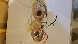
3 lbs. 15 oz. each picture attached. They are identical Talema 4365-P1S2 toroids. i have 4 - 15,000 mfd caps to use for input filtering, I also have an 8 amp bridge, but may upgrade that to 25 amp. i'm using this to power a single channel class D Chinese amp for my LFE subwoofer. Supposed to be 350 watts but realistically hoping for 100-150 watts into 8 ohms.
TonyTecson has a good idea. Use the Bulb Tester.
In series it will always be 20 - 0 (Ct) - 20, unless something is wrong with the windings. But it may not be in phase.
Without a 2 channel scope you can not Directly visually screen check the phase.
But you can easily check the phase with a DMM. Just read from one 20 to the other 20. It should read 40.
If not, reverse the connections on just one secondary. Re-test, it should read 40.
Last edited:
I have two identical torroid transformer laying around. Both have 117 Volt single primaries and two 20VAC 5 amp secondaries. I want to connect the two secondary windings in series on each transformer to get 40VAC 5 amps. Then connect the two transformer secondary windings out of phase to get 56-0-56. My question is: What is the total wattage for both transformers connected this way? I pretty sure I have 40VAC X 5amps = 200 watts for each transformer, but what happens to wattage when they are connected out of phase?
RE: Talema 4365-P1S2
I am trying to do the same thing (double the voltage) with the same transformers, can you tell me your results. Also I am trying to verify the standard wiring.
Thank you,
Bob
123bob@comcast.net
Two transformers to power single +/- power supply
My question is probably a little bit different from that of the OP.
For a project the requirement is for a 300-400 VA transformer to power a dual rail (+/-) power supply. What I can get at this moment are two smaller (200 VA) toroids.
Is it ok to power one dual-rail power supply board with two toroids?
Is it ok to power one dual-rail power supply board with two toroids?
Yes, that should not be a problem at all. Post your schematic.
My question is probably a little bit different from that of the OP.
For a project the requirement is for a 300-400 VA transformer to power a dual rail (+/-) power supply. What I can get at this moment are two smaller (200 VA) toroids.
Is it ok to power one dual-rail power supply board with two toroids?
That even leaves you with two options: 1) rectify each secondary winding separately and stack the rectified voltages, or 2) connect the primaries in parallel and the secondaries in series and use only one rectifier bridge as if you had a symmetrical (double) secondary winding. The last option (2) should give the best (most equal) loading of the two transformers.
That even leaves you with two options: 1) rectify each secondary winding separately and stack the rectified voltages, or 2) connect the primaries in parallel and the secondaries in series and use only one rectifier bridge as if you had a symmetrical (double) secondary winding. The last option (2) should give the best (most equal) loading of the two transformers.
I would avoid running 2 Toroids in parallel unless you are positive the match to within 0.1% in voltage and regulation (Choose whatever tolerance makes sense, this is what I have used in the past with success). Typically run of the mill Toroids will not meet this spec and the Toroids will cook each other up.
You are better up stacking the Toroids (one per rail). If you have to wire them in parallel, do it after they are rectified. Gives you some margin.
In either case, monitor heat and voltages over a 24 hour period before committing. Needless to say, use a mains bulb before prototyping this.
Last edited:
I would avoid running 2 Toroids in parallel unless you are positive the match to within 0.1% in voltage and regulation (Choose whatever tolerance makes sense, this is what I have used in the past with success). Typically run of the mill Toroids will not meet this spec and the Toroids will cook each other up.
You are better up stacking the Toroids (one per rail). If you have to wire them in parallel, do it after they are rectified. Gives you some margin.
In either case, monitor heat and voltages over a 24 hour period before committing. Needless to say, use a mains bulb before prototyping this.
Absolutely true, therefore I suggested to connect the secondaries in series so their differences in output voltage will not allow one to source the other.
For parallel coupling of secondaries, they should each have a rectifier first so no return currents are possible.
- Status
- This old topic is closed. If you want to reopen this topic, contact a moderator using the "Report Post" button.
- Home
- Amplifiers
- Power Supplies
- Dual Transformer Power supply Question