Hey folks,
I hope this is the right section for this, I typically am only in the car audio section here, but I am feeling a bit out of my depth with this AVR 3700.
The AVR is only 2 years old, it was a warranty replacement from HK for a AVR2750 (IIRC) that also had the power supply go out.
First off, let me lead by saying I know these AVR's are not the quality that they used to be. My original AVR500 lasted more than 10 years (in fact it's almost 16 years old and a buddy is still running it daily) but I digress. I have been through a steady supply of HK AVR's for the last 5-6 years. I do not want to buy a new one, and I think there is a good chance this one can be fixed.
The attached PDF shows the part of the SMPS in question. The full service manual was to large to attach, but Click Here for a copy hosted on my web site. The other morning while I was at work, wife was in the kitchen making coffee. Heard a pop, nothing was on in the entertainment center. She couldn't locate what popped and forgot about it. A few hours later my 6 year old son tried to turn on the AVR to watch TV and there was another pop and he said "orange stuff flashing on top of it". Long story short, I opened it up and IC91 OB2358L is blown apart and all of it's current sense resistors are severely overheated as well. It looks like this is a low voltage supply and this SMPS chip is driving the windings of a small xformer directly. I am hoping that the issue was just a cheap SMPS chip, but I am going to pull the 24V linear regulator and test that as well in case it failed.
/TLDR: Do any of you have experience repairing these units? Is there a common failure here or is there something further I should be investigating before I order parts.
Thanks in advance!
Sincerely,
Jason
Attachments
The most important step is to find out the reason therefore.Hey folks,
I hope this is the right section for this, I typically am only in the car audio section here, but I am feeling a bit out of my depth with this AVR 3700.
The AVR is only 2 years old, it was a warranty replacement from HK for a AVR2750 (IIRC) that also had the power supply go out.
First off, let me lead by saying I know these AVR's are not the quality that they used to be. My original AVR500 lasted more than 10 years (in fact it's almost 16 years old and a buddy is still running it daily) but I digress. I have been through a steady supply of HK AVR's for the last 5-6 years. I do not want to buy a new one, and I think there is a good chance this one can be fixed.
The attached PDF shows the part of the SMPS in question. The full service manual was to large to attach, but Click Here for a copy hosted on my web site. The other morning while I was at work, wife was in the kitchen making coffee. Heard a pop, nothing was on in the entertainment center. She couldn't locate what popped and forgot about it. A few hours later my 6 year old son tried to turn on the AVR to watch TV and there was another pop and he said "orange stuff flashing on top of it". Long story short, I opened it up and IC91 OB2358L is blown apart and all of it's current sense resistors are severely overheated as well. It looks like this is a low voltage supply and this SMPS chip is driving the windings of a small xformer directly. I am hoping that the issue was just a cheap SMPS chip, but I am going to pull the 24V linear regulator and test that as well in case it failed.
/TLDR: Do any of you have experience repairing these units? Is there a common failure here or is there something further I should be investigating before I order parts.
Thanks in advance!
Sincerely,
Jason
Maybe the detailed descriptions in the infineon/ON-Bright datasheets are helpful - go to
https://www.infineon.com/dgdl/Infin...n.pdf?fileId=db3a304412b407950112b418cbe626ac
(Datasheet) OB2358L - Current Mode PWM Power Switch (7-page) : On-Bright Electronics Datasheet PDF
and ask here for application notes
On-Bright Electronics--Brighten Your Life
burned and cheap electrolytics are good known reasons particularly on new harman audio multi channel amplifiers.
Thank you for the data sheet, when I looked it up this morning I was only coming up with a generic Asian data sheet with only a spattering of English throughout.
The first thing I did was look for vented caps. I was actually expecting a cap to be the "pop" my wife heard.
I will continue to look for other faults, I was just hoping there is a common issue. I understand 12v smps fairly well as used in car audio amplifiers, but these avrs have a lot more going on. It is just a lot to take in. Seems like there is a separate supply for each voltage they needed to derive.
I'll keep working on it. Thank you for your reply!
Jason
Check for dry electrolytic capacitors (by measuring capacitance) in standby SMPS section. In certain conditions a dry capacitor can make a IC pop like that.
Check the parts around the failed IC for damage (open or shorted), since the IC interfaces low voltage with high voltage, and in case of failure high voltage leaks to low voltage nodes, check zeners intended to control that.
Some programmed obsolescence issues or mistakes from Harman in this circuit:
- Designing with small electrolytic capacitors is outdated, particularly in standby supplies, these always dry, solution is bigger better electrolytics (Alum Poly for hi-current low-voltage) or ceramics.
- The reputable-worldwide-brand Infineon IC is used for RUN power supply, and the unknown-Shangai-brand OnBright IC is used for standby supply, permanently on. It could have failed just because the manufacturer is immature. A good Tinyswitch from PowerIntegrations is what they should have used if they had a bit of patriotism and common sense. Good luck finding a replacement IC.
Thanks Eva! I'm going to try to spend a few more hours today doing fault finding.
I hadn't considered that I might have trouble finding a replacement smps controller. The BOM in the service manual lists the same infineon part for both supplies. The schematic disagrees. What is left of the ic in my power supply seems to match the schematic. I haven't compared the data sheets yet, but hopefully there will be an infineon part that is compatible and I won't have to try to source something not likely to be stocked in the US.
I can't tell you how disappointed I was when I opened this up, just the over all build quality in general. I realize it's not built for the same environment as the audio equipment I normally tinker with, but if this had been a car audio amp I had opened, I would have guessed that it came from the bottom of the barrel - - pyramid or Pyle or some such nonsense. I would have never thought it was some companies $1k+ flagship product.
Thanks again for the advice. I'll hopefully get further with it today.
Sincerely,
Jason
Quick update:
I went quite a ways down stream of the on-bright IC and did not find any issues. I tested the 24V regulator and most of the transistors in the immediate vicinity. I found every one of the current sense resistors are way out of spec. I also D928 is bad.
I was unable to find a pin compatible SMPS driver IC. Truth be told I didn't look that hard. I ended up ordering 10 of the original part from China. Hopefully I get authentic parts. I still need to check caps, I got side tracked with the flood here and have not done that yet. If I do not find anything else, I'm going to go ahead and replace the IC, the diode and the CS resistors and hope for the best.
I will let you all know when I know more. Thank you all again for your time!
Jason
Well, I am still lost... I got my eBay OB2358s, I replaced the bad zener, I checked components until I was blue in the face-- I found nothing else. I put it all back together and it blew the fuse instantly.
I went on to troubleshoot more. I pulled and tested the bridge rectifier and the TO-220 rectifiers. I checked the two mosfets for the big power supply. I found both the small caps in parrallel with the mosfet gates were blown-- one split in half, no idea why, the transistors are fine. I was at my wits end and pulled the bridge rectifier and tried to power it. It still blew the fuse. There are just two common mode chokes and some X/Y caps between the AC input and that rectifier.
I realized I had overlooked something. Two diodes that are on the bottom of the board and are actually the input to the supply that originally failed. They were both shorted. They were SMD 1KV 1A diodes, I did not have any, so I bodged in some 1N4007. After this it quit blowing fuses, but I still do not have any of the supplies coming up.
The OB2358 has 330VDC on the drain connections (pins 5&6), it has 12Vdc on VDD. 0V on the feedback pin, although it makes my meter freak out for some reason, like there is AC on it or something. I do have a scope, but I haven't gotten that far yet. The CS pin is also at 0V. The standby supply is producing less than a volt on the secondary side of the transformer.
I am not ashamed to admit I don't understand how these bootstrapped supplies work very well. I am trying to learn, I finally had to step back from this one. I am hopeful something I mentioned here will help someone help me, but worst case scenario-- I am stubborn and it will probably end up working or being a ball of fire on the bench!
Thanks,
Jason
Those little integrated switchers sometimes keep drawing short current pulses at a low frequency for self powering (at least Power Integrations chips). Otherwise the standby switcher is probably attempting to start but failing (over-current, open feedback) or toasted PC92 opto (shorted phototransistor), also D928 could be damaged, or maybe the zener handled the failure current but at a high voltage that the opto didn't survive. I suppose you checked R922, R923, and current sense resistors replaced are the right value.
I see no gate capacitors in schematic, what capacitors (reference designator) did you find damaged? C916,C938?
There is a chance the failure of the big SMPS caused a transient in mains voltage, the MOV is 560V (plus resistive drop >600V easily), the little OB chip can only withstand 600V, subtract from that 50~150V of flyback reflected voltage (can become toasted before the MOV starts conducting), and note that there is no resistor in series with the D901,D902 that you replaced (to temporarily arrest the surge).
Last edited:
Thank you for the reply, it is much appreciated. I'm fairly certain that I checked r922/23, but I will double check when I get to go back to the shop next Monday. I replaced d928 after the original fault, I have rechecked it as a normal diode, and it is still intact, but I can change it again if it seems a likely candidate.
The gate capacitors I was talking about is on the next page in the service manual. I hosted the full manual, but only uploaded the one page to the forum because it was too large. The capacitors in question are C983/984, they are found on page 167 of the full service manual linked in my OP. I'm not sure why they failed, the 11N80 fets as well as their gate resistors are 100% OK.
The opto-isolator was kind of where I was headed next, it seemed the logical next step. I'm not sure how to test one though and Perry Babin had it drilled into me not to just start shotgunning parts . I'm sure there is a way to test a opto-isolator though, if I have free time at work this weekend I'll do my homework and learn how... I expect it's just a matter of driving the led side and seeing if the transistor conducts...
Thank you again for taking the time to share your insight.
Sincerely,
Jason Campbell
The gate capacitors I was talking about is on the next page in the service manual. I hosted the full manual, but only uploaded the one page to the forum because it was too large. The capacitors in question are C983/984, they are found on page 167 of the full service manual linked in my OP. I'm not sure why they failed, the 11N80 fets as well as their gate resistors are 100% OK.
The opto-isolator was kind of where I was headed next, it seemed the logical next step. I'm not sure how to test one though and Perry Babin had it drilled into me not to just start shotgunning parts
. I'm sure there is a way to test a opto-isolator though, if I have free time at work this weekend I'll do my homework and learn how... I expect it's just a matter of driving the led side and seeing if the transistor conducts... Thank you again for taking the time to share your insight.
Sincerely,
Jason Campbell
Last edited:
Sometimes SMD capacitors fracture and become shorted, this depends on mechanical stress and precision in production process. Replace C983/C984 by 470pF 1kV C0G. Be careful not to touch capacitor terminations with soldering iron tip and not to use excessive temperature or soldering time, use hot air machine if available.
Basic tests for a optoisolator like PC92 (EL817B) are:
- No collector to emitter short in phototransistor.
- No short across photodiode, correct forward voltage ~1V at multimeter diode test current.
- Remove the part if needed, apply to photodiode in forward direction something like 1~10mA with a battery or bench supply and a resistor (or multimeter diode test current), load the phototransistor collector with a resistor to same or another battery or bench supply, ground the emitter, measure phototransistor current, compare with datasheet. In this case EL817 datasheet states 130% to 260% current transfer ratio (CTR) for If=5mA and Vce=5V, so with If=5mA and a 5V collector supply (small series resistor) Ic should be 6.5~13mA.
If the zener was replaced once lets suppose it's OK, the opto was not replaced. I suppose the zener was shorted or open due to overvoltage, similar fate for the opto in that case.
C983/984 are through hole parts, disc style capacitors. I replaced them with 560pF 1kV that I had in stock. I know it is not ideal, I will order the exact replacements when I get a complete list together.
The zener was shorted on initial testing. I did not have a 20v zener in stock, so I used a 15V .5A and 5V .5A in series, I will get the proper zeners when I find all the issues, but for now my replacement seems to be ok. If the optoisolator checks out fine and the zener is still in question I will pull it and test is to see if it clamps at or near 20V.
Thank you for the instructions on testing the optoisolator. I will check it on my day off Monday.
If I could ask one more question, something I forgot to update yesterday: TH91, found in the upper right corner of the SMPS schematic attached above, has failed while I was testing. I believe it is a PTC thermistor(?), the part number was under silastic and is unreadable now-- Do you know how to decipher the part number in the schematic, DSC-2.5D-20. I pulled a similar part from my old AVR247 that has a failed video board. I would rather order the correct exact replacement, but I am not even 100% sure that it is a thermistor.
Thanks,
Jason
Last edited:
I may have figured out the thermistor on my own. It looks like it is NTC, 2.5 ohms and 20mm diameter. That's the best I can figure out from the korean website of what I believe is the manufacturer. I'm guessing that for inrush current limiting I am not worried about the resistance/temp curve or anything like that? I also found a part of a datasheet that seemed to indicate the thermistor can handle up to 8 amps. Armed with that I think I can find a suitable replacement from a US distributor.
Thanks!
Jason
Thanks!
Jason
Well, I am back and unfortunately have still not been successful.
The optocoupler tested good. Pulled it and tested as described, I also varied the current to the LED and insured that the emitter current followed it. It seemed ok.
I found another diode bad, D914. I know I checked this one in the beginning and it was ok, but it looked pretty hashed and I tested it today and found it open. I replaced it with a new 18v zener.
I retested R922 and R923, they are both dead on in spec. I also tested R926 and R927 and they were fine until I did something stupid and powered the supply with out the OB driver in place. It blew the two 1.2M resistors right off the board. I patched that up and replaced the 18V zener again.
Still is a giant no-go. I'm beginning to wonder if these OB drivers I ordered off ebay aren't junk. I do have a broken AVR247 that I used before this "upgrade" and I think there is an OB SMPS driver in there as well, if worst comes to worst I will pull it and see if I get different results.
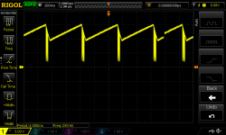
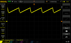
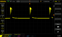
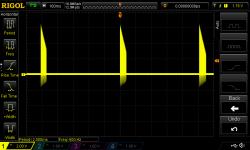
Attached below are some screenshots of the waveform on each pin on the OB driver. All SS are referenced to PG and are named for the pin probed. I'm not sure what the deal is with the sawtooth wave on both Vdd and Vdd-g. Vdd-g measures about 12Vdc and falls off to about 9Vdc and then climbs again. Vdd does the same thing, but goes up to about 13.5Vdc and down to 9Vdc. The FB pin is odd as well, it makes my DMM go nuts, but if measured as AC it measures about 1.4-2.5Vac, from looking at the trace, I am wondering if it isn't the OB chip trying to start up and then failing. CS pin has some weird spikes as well. The last trace is where I was hoping and expecting to see DC. It is taken at the cathode of D921. The cathode of D943 looked almost identical, so I did not SS it. I do measure about 1.5Vdc on the cathode of both of those diodes.
I don't know exactly what to be checking out at this point. I feel like I have exhausted every possibility...
Thanks,
Jason
The optocoupler tested good. Pulled it and tested as described, I also varied the current to the LED and insured that the emitter current followed it. It seemed ok.
I found another diode bad, D914. I know I checked this one in the beginning and it was ok, but it looked pretty hashed and I tested it today and found it open. I replaced it with a new 18v zener.
I retested R922 and R923, they are both dead on in spec. I also tested R926 and R927 and they were fine until I did something stupid and powered the supply with out the OB driver in place. It blew the two 1.2M resistors right off the board. I patched that up and replaced the 18V zener again.
Still is a giant no-go. I'm beginning to wonder if these OB drivers I ordered off ebay aren't junk. I do have a broken AVR247 that I used before this "upgrade" and I think there is an OB SMPS driver in there as well, if worst comes to worst I will pull it and see if I get different results.
Attached below are some screenshots of the waveform on each pin on the OB driver. All SS are referenced to PG and are named for the pin probed. I'm not sure what the deal is with the sawtooth wave on both Vdd and Vdd-g. Vdd-g measures about 12Vdc and falls off to about 9Vdc and then climbs again. Vdd does the same thing, but goes up to about 13.5Vdc and down to 9Vdc. The FB pin is odd as well, it makes my DMM go nuts, but if measured as AC it measures about 1.4-2.5Vac, from looking at the trace, I am wondering if it isn't the OB chip trying to start up and then failing. CS pin has some weird spikes as well. The last trace is where I was hoping and expecting to see DC. It is taken at the cathode of D921. The cathode of D943 looked almost identical, so I did not SS it. I do measure about 1.5Vdc on the cathode of both of those diodes.
I don't know exactly what to be checking out at this point. I feel like I have exhausted every possibility...
Thanks,
Jason
Attachments
Rare to blow 1.2M resistors with voltage, but easy to damage mechanically.
The waveforms show normal fault/restart cycle in that kind of chips. There is a short/open in the power path or a problem with feedback path. The chip is either shutting down due to:
- C918 voltage falling before enough charge comes from D911 to keep stable supply voltage to the chip. This is a timed operation. The IC starts at ~12.5V supply and must complete startup before it has drained C918 to about 7V. C918 could be semi dry or something could be open in this path, or there could be a short in any of output rails (all output voltages rise in sync as windings are coupled).
- Permanent overcurrent timeout (burst mode time exceeded, the IC continuously terminating pulses due to maximum current reached). This can happen due to shorted diode or transformer, or with open or shorted feedback depending where.
The waveforms have to be captured in more X detail, to see individual pulses, apart from showing repetition envelope due to periodic shutdown.
The IC does not seem to be faulty at first sight.
The resistors are completely my fault. When I replaced the OB driver I put it in a socket just in case I needed to swap more than once. I had it out of the socket when I powered it up. It blew part of the trace to R926, blew R926 up at about a 45° angle and shorted D901/902 and D914 again...
I have checked almost every cap on the board in circuit with just my DMM. I know that in circuit testing can give unreliable results. I will pull C918 and check it with my proper capacitance tester.
As for a possibility of a short existing after the transformer, I currently have the power supply board completely disconnected from the amp. Would I be able to lift the cathode of D943 and D921 to narrow down where I need to be fault finding... It looks like if I lift D921 I break the feedback loop, can I just supply the OB chip 2.5Vdc on the FB from another source just to get it to run long enough to find out if the issue is the transformer or not?
I am somewhat worried that the transformer is going to be the problem. It might be tough to source a replacement. I will try to get some better screenshots of the waveforms. I had a hell of a time getting it to trigger on the ones I finally got. I have 100khz noise all over this supply and my scope like that way more than what I was trying to get!
Thank you again for your time. I am working 12hr midnights now through the week, but with any luck will get back to the receiver on Friday afternoon or Saturday during the day.
Jason
Ok, I am back...
C918 checked out well inside spec.
I lifted the cathode of D943/921, it continues to behave the same way.
Grasping at straws I pulled Q909/914/915 and tested and they are all good.
I pulled IC96, a SMD adjustable vreg of sorts, it tested fine per it's data sheet.
I'm pretty sure I am out of parts to test. I pulled the small xformer and have been trying to figure out a way to test it.
I do not have a high end LCR meter, but I do have one of those cheap component testers which are supposed to measure inductance. I could only get it to give me resistance measurements on the transformer, no inductance. I am not sure if this is a problem with the meter or xformer. I had what I thought was a genius idea, but in hind site may not have been... I put the little standby xformer on a breadboard, I got a little 110/12V xformer I had and I hooked up one of the primary coils to the 12V xformer. It wasn't explosive, but it did melt the jumper wires before the fuse blew...
Initially I assumed that this meant the transformer had shorted. A few minutes later I realized that these tiny transformers are probably for much higher frequency and I may have just saturated it with the 60hz ac.
I'm pretty stubborn, but I am starting to feel defeated. I'm sorry to keep bugging you all, but might anyone have any more advice for me?
Thanks,
Jason
I told you to capture the waveforms during "hicup mode" in more detail, so that each switching cycle can be analyzed, this will reveal the problem. The OB chip will only abort startup if primary overcurrent, or +VDD capacitor drain, or feedback requesting full power (no feedback) for long enough time.
Switching frequency of the OB chip is fixed to 50khz. Flyback transformers are gapped and are among the lowest inductance ones found in SMPS. The inductance of the primary of these small flyback transformers can be in the range from 200uH to 2mH. The inductance of the secondaries can be 50 times lower (primary divided by turns ratio squared, turns ratio for these low voltages is around 5~30, the usual rule is that output voltage multiplied by turns ratio is in the 60V~180v range). These 2 datasheets show off-the-shelf models, representative of most models.
premiermag.com/pdf/pol-12208.pdf
premiermag.com/pdf/pol-12216.pdf
A 700uH primary will exhibit an impedance of 0.22 ohms at 50hz (2*pi*f*L), so it's not the right frequency to measure it. Saturation current will be less than 2A for these small models, so 0.4V amplitude is all needed to saturate a 700uH primary at 50hz. An audio generator capable of 10~20khz, or an oscillator producing 10~50khz square wave at low voltage in a breadboard is recommended as a minimum. Low power SMPS transformers rarely fail but it could be the case (or something obvious is being overlooked).
Having such an oscilloscope and ability to get parts and test components, I though you would have more knowledge about post-1990s electronics.
Another recommendation is to get some transformers from old audio equipment and wire secondaries in series to get isolated 100V AC or so, to safely test the SMPS circuit with power. In the primary a light bulb in series is recommended to protect from mistakes, and a variac if available, to test the flyback at low and high input.
Last edited:
Eva, thank you again. I had intended to capture waveforms again yesterday while I had time to work on this. I wanted to make sure I worked through the other stuff you mentioned, and I got carried away pulling and testing components, and then I got frustrated and went to work on a car audio amp (which I can normally repair in my sleep).
I thought I mentioned earlier in the thread that my knowledge is hobbyist or, as I am learning, probably even less. The little I know is "self taught" and there are clearly big gaps in my knowledge. I really apologize, I realize that probably none of you come here because you want to teach someone electronics design and repair. I'm trying not to be a complete idiot, and am doing my best to understand the concepts we are talking about. Obviously I am not doing so hot on that front.
The reason I have the tools and parts stock I do is just because of the car audio repair work, it's a hobby and I collect (horde) and fix old amps. I enjoy the problem solving and I just generally like to fix things.
Anyhow, I will read the documents you linked and when I get a day off work again I will try to get more detailed waveforms. Thank you very much for your time.
Sincerely,
Jason
Every designer should teach some techs, for work we rely on evidence that can be discussed with few people.
I just took these pictures from a little flyback I designed. Mains isolation transformer used for easier measurements.
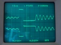
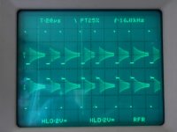
Top trace shows one of the secondaries, the -12V one, 10:1 normal probe.
Bottom trace shows primary at 230V mains, 100:1 SMPS probe (1200V max.)
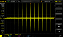
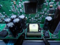
1st picture shows a single cycle in detail. 2nd picture shows more cycles, irregular operation is due to the fact that TNY chips employ pulse skipping regulation for lowest idle losses. 3rd picture shows the little 5-output flyback.
I just took these pictures from a little flyback I designed. Mains isolation transformer used for easier measurements.
Top trace shows one of the secondaries, the -12V one, 10:1 normal probe.
Bottom trace shows primary at 230V mains, 100:1 SMPS probe (1200V max.)
1st picture shows a single cycle in detail. 2nd picture shows more cycles, irregular operation is due to the fact that TNY chips employ pulse skipping regulation for lowest idle losses. 3rd picture shows the little 5-output flyback.
Attachments
Last edited:
- Status
- This old topic is closed. If you want to reopen this topic, contact a moderator using the "Report Post" button.
- Home
- Amplifiers
- Power Supplies
- Help with a Harman Kardon AVR3700 SMPS