Hi guys, I need some advice regarding power supply issues. Input at 230V goes through power rectifier IN5408 X4. The output I'm getting is around 460V. Actual power caps is 270uf/450V but diagram shows 220uf/450V. If replace to 220uf will i get higher or lower value.
Attachments
Ok. But the voltage for B+ at 460V is a bit high. My screen voltage at pin 4 is around 450V which is not recommended for EL34 max is at 425V.as far as i am concerned, there is little difference between 220 and 270ufd..
Noted but just wondering the design why never take into consideration the voltage as EL34 screen voltage is at max 425V.to reduce voltage is easy, insert some resistance in the B+ to lower the voltage...
Agree.
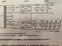
You seem to be using the nominal 320V tap today, which is too high, not only because of EL34 which has some flexibility but much worse, because of C12/C9 which are right on the edge or beyond.
So as RussC suggests, go to the next lower tap, which by the way is a much better solution than adding a resistor in series, because output voltage will be way more stable and predictable.
So as RussC suggests, go to the next lower tap, which by the way is a much better solution than adding a resistor in series,
yes to this.....better than wasting heat on a resistor...
The output voltage isHi guys, I need some advice regarding power supply issues. Input at 230V goes through power rectifier IN5408 X4. The output I'm getting is around 460V. Actual power caps is 270uf/450V but diagram shows 220uf/450V. If replace to 220uf will i get higher or lower value.
Vsecout = Mains voltage/Rated Primary voltage * Rated secondary voltage * {1+transformer regulation}
If the transformer is 230:280Vac 10% regulation and mains is 6% high (243.8Vac) then the secondary voltage is:
Vout = 243.8 / 230 * 280 * {1+0.1} = 326.5Vac
Rectify that and store the peak voltage after allowing for 0.5Vf across each rectifier diode and you have 460.7Vdc stored on the capacitor.
Learn to do the arithmetic. It's not difficult.
This is an approximation to the peak voltage of a sinewave.Your schematic shows transformer taps at 280/320/350V.
280x1.4 = 392V.
You are misleading anyone who believes that it can simply be applied to any mains transformer.
The rCC shown in post1 will try to charge the capacitors with an enormous initial current.
I suggest you add some resistance before or just after the power rectifier.
This will extend the life of the rectifier and of the capacitors.
The reason for the high initial current is the small value of "r"
It might be anywhere from 10r to 20r and even 20r would allow an initial pulse of ~23Apk through the rectifier and into the capacitors.
Add two or three Power Thermistors or Power resistors, to reduce the current peak.
My main is 230V. Voltage variation is +-5%.Andrew, I'm still learning so thanks for the info regarding 10% transformer regulation.
However, OP is from Singapore so don't know what mains voltage variation they are subject to.
Have you discovered a new kind of Physics?This is an approximation to the peak voltage of a sinewave.
You are misleading anyone who believes that it can simply be applied to any mains transformer.

If so, publish your results in some peer reviewed Physics or Science and wait for grinning approval .... or laughter.
What is YOUR definition of the peak value of a sinewave? Inquiring minds want to know.
WHERE do you read that?I see NO mention of "rCC" on post#1, either typed or in the picture supplied?The rCC shown in post1 will try to charge the capacitors with an enormous initial current.
Are you answering to this post?
Sure, but billions of power supplies do NOT add any extra resistance and work fine since .... forever.I suggest you add some resistance before or just after the power rectifier.
This will extend the life of the rectifier and of the capacitors.
Which is ....... ?The reason for the high initial current is the small value of "r"
So?It might be anywhere from 10r to 20r and even 20r would allow an initial pulse of ~23Apk through the rectifier and into the capacitors.
You discovered nothing new, semiconductor manufacturers know that, so much so that they, precisely, specify a surge current value in the datasheets.
For 1N5408, what we are talking here, Vishay (who should know) says:
1N5400, 1N5401, 1N5402, 1N5403, 1N5404, 1N5405, 1N5406, 1N5407, 1N5408
Vishay - manufacturer of discrete semiconductors and passive components Vishay General Semiconductor
Revision: 01-Aug-13 1 Document Number: 88516
For technical questions within your region: DiodesAmericas@vishay.com, DiodesAsia@vishay.com, DiodesEurope@vishay.com
THIS DOCUMENT IS SUBJECT TO CHANGE WITHOUT NOTICE. THE PRODUCTS DESCRIBED HEREIN AND THIS DOCUMENT
ARE SUBJECT TO SPECIFIC DISCLAIMERS, SET FORTH AT www.vishay.com/doc?91000
General Purpose Plastic Rectifier
FEATURES
• Low forward voltage drop
• Low leakage current
• High forward surge capability
..........
PRIMARY CHARACTERISTICS
IFSM 200 A
..........
MAXIMUM RATINGS (TA = 25 °C unless otherwise noted)
Peak forward surge current 8.3 ms single half sine-wave superimposed on rated load ...... IFSM ..... 200 A
Not bad, but two or threeAdd two or three Power Thermistors or Power resistors, to reduce the current peak.
One is enough, in series with primary.
And typical values hover around 5 ohms.
IndeedLearn to do the arithmetic. It's not difficult.
look again at post1 schematic.
C12 & C9 = CC
the resistances of the preceding wiring, power rectifier and transformer add up to the "r" that is often ignored.
That capacitor input filter is an RC filter but the R part is very small, written as rC or rCC in my previous posts where Members have not realised they have implemented an RC filter.
Find a Power Thermistor that has significant energy absorption and can tolerate a starting voltage differential of 460Vpk. There will be some.
Last edited:
- Status
- This old topic is closed. If you want to reopen this topic, contact a moderator using the "Report Post" button.
- Home
- Amplifiers
- Power Supplies
- Power supply output