Sorry if this is a lame question, but will this work for the negative bias rail? I can't find any schematics in the net on this sort of:
or, same thing if I want the higher HV - with swapped 2 &3.
Tnx.
An externally hosted image should be here but it was not working when we last tested it.
or, same thing if I want the higher HV - with swapped 2 &3.
Tnx.
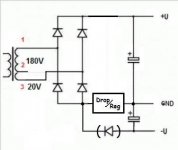
Ignoring diode drops for simplicity, terminal 1 will swing between 0V and +254V, good to charge the upper cap with +254V relative to ground.
Terminal 2 will do exactly the same.
Terminal 3 will swing between -28V and +283V.
Yes, you can get -28V on the lower capacitor.
Just in case use a very good diode there, 2 x 1N4007 in series even better.
Terminal 2 will do exactly the same.
Terminal 3 will swing between -28V and +283V.
Yes, you can get -28V on the lower capacitor.
Just in case use a very good diode there, 2 x 1N4007 in series even better.
Thanks for clear explanation, how about this, to add a bit of the second half wave. The 0.47uF picked for the -U rail load approx. 10mA (+3mA/-1mA).
Oh, the cap will just stay charged, so how to modify this version? Half-way creates a bit of hum.
An externally hosted image should be here but it was not working when we last tested it.
Oh, the cap will just stay charged, so how to modify this version? Half-way creates a bit of hum.
Last edited:
I mentioned that the load be close to constant, with the load resistor permanently attached across the -U. My concern was if the cap gives some high voltage spikes which could fry the diodes.
If evr kept as is, I assume a single choke in GND line will do a good job for both rails, right?
If evr kept as is, I assume a single choke in GND line will do a good job for both rails, right?
> will this work for the negative bias rail?
No.
You get +28V and -28V DC.
> Sorry if this is a lame question
Not lame at all. The reason it fails is hard to see. JM is a very smart guy. I'm dumb so I checked with someone dumber, SPICE. Unless I drew it wrong, this does not do what you want.
No.
You get +28V and -28V DC.
> Sorry if this is a lame question
Not lame at all. The reason it fails is hard to see. JM is a very smart guy. I'm dumb so I checked with someone dumber, SPICE. Unless I drew it wrong, this does not do what you want.
Attachments
It does exactly what it's needed:
An externally hosted image should be here but it was not working when we last tested it.
No. A choke in the common return line will merely try to equalise the ripple currents, not minimise them.Shef said:If evr kept as is, I assume a single choke in GND line will do a good job for both rails, right?
Keep it simple. Then you have a much better chance of debugging it, and it will behave in a more predictable way if at some point in the future it develops a fault.
Sorry if this is a lame question, but will this work for the negative bias rail? I can't find any schematics in the net on this sort of:
An externally hosted image should be here but it was not working when we last tested it.
or, same thing if I want the higher HV - with swapped 2 &3.
Tnx.
So which one do you need?
1) A split supply with a rail below GND or;
2) A higher HV and only a single supply?
More importantly, what are you trying to do? That is, is the solution you are trying to achieve addressing the objective you are pursuing in the most simple and effective way.
More importantly than that, is the objective a rational one, or can it be achieved more effectively from a different approach.
Please excuse the questions in regard to logic, it's my Vulcan DNA
PRR, I knew it will work, I rather wanted confirmation from others there is no rock under the water surface, as my major skill is not exactly PSUs, but of course I designed and built some. JM, indeed, put it in a very clear manner. The flaw in your reasoning is that the +28V will be outnumbered by the +254V so it should make no influence. I appreciate any input, thanks. Even as lame as my request – it makes the mind spinning.
In fact I tried this and did not like the slow grow on -28V rail, but that could be just a coincidence as my multimeter started going nuts the same afternoon, waiting for the ordered replacement. So I thought if I could use the second half wave, and that’s why I mentioned the type of load.
The choke is a separate request, some filtering won’t hurt, right? For that I also wanted the confirmation to my suspicion it might not be the best, tnx DF96, I see, equalizing, right.
What am I trying to achieve? Make a PSU out of a single inexpensive and quite ok quality mains AnTek toroid trafo on hands so “the different approach” is out of question. I think I will add a simple filter on TIP50 to +U, proven working well, performing a bit poorer than on MOSFET but reliable as a brick. For the –U I use LM2924.
Came back to it today, trying to put it in practical use, and. .. it does not actually work.
When I quickly breadboarded it a month ago, well, the negative rail did make it to -29V, but suspiciously slow, in several seconds. I thought maybe the diode was faulty, got some extra ones, not a big deal.
Now, when I put just a 3 mA load to it the voltage drops to -2V. .. that explains the slow filter cap charge. Can't see what wrong is with it, checked everything, both halves od secondary separately do what they supposed to do. .. banging my head against the wall, but that does not help either. .. Anyone has any idea what is with this circuit?
Sure, the circuit is exactly this one:
All diodes are 1N4007, the el caps are the common 80uF x 400V & 1000uF x 50V, the trafo is 50VA Antek AS-05T200, the wires are stranded copper 300V insulation, the solder is rosin core KSC-2508, the air temperature is 24 C, I'm on planet Earth, Solar system, right between of Alpha Centauri and Sirius, in the Orion arm of the Milky Way galaxy. The cat has been out since noon and is not participating. ..
The resistive load of 10K applied across the top cap, the +U drops to +245..250 V, expected, or, if idle goes to +262 V.
The resistive load of 820 ohms applied across the bottom cap, the -U drops to -2 V, why so? Without the load it _slowly_ raises back to -29V.
An externally hosted image should be here but it was not working when we last tested it.
All diodes are 1N4007, the el caps are the common 80uF x 400V & 1000uF x 50V, the trafo is 50VA Antek AS-05T200, the wires are stranded copper 300V insulation, the solder is rosin core KSC-2508, the air temperature is 24 C, I'm on planet Earth, Solar system, right between of Alpha Centauri and Sirius, in the Orion arm of the Milky Way galaxy. The cat has been out since noon and is not participating. ..
The resistive load of 10K applied across the top cap, the +U drops to +245..250 V, expected, or, if idle goes to +262 V.
The resistive load of 820 ohms applied across the bottom cap, the -U drops to -2 V, why so? Without the load it _slowly_ raises back to -29V.
In this circuit the two PSU halves interact. They are almost in series, so the negative supply is affected by the impedance of the positive supply. Placing a load on the negative supply will raise the positive supply. As the positive supply has higher impedance (due to smaller caps) you just get a balance shift. Difficult to explain, but try drawing the circuit with a pair of bridge diodes omitted (upper right, lower left) so you can visualise what happens at AC peak.
Ignoring diode drop to simplify anlysis, the "20V tap" connected to the bias diode swings between +280V where it passes no current (into the bias capacitor) because bias diode is reverse biased and within PIV rating and -28V where it forward biases bias diode and charges bias capacitor to -28V .
And it charges it *fast* , in the order of 100 milliseconds.
So slooooowww charging plus heavy voltage drop hint at an important resistance in series, in the order of , say, 10k ohms.
Check your wiring, all the path, transformr continuity, the bias diode itself.
So what you describe
And it charges it *fast* , in the order of 100 milliseconds.
So slooooowww charging plus heavy voltage drop hint at an important resistance in series, in the order of , say, 10k ohms.
Check your wiring, all the path, transformr continuity, the bias diode itself.
So what you describe
The "important resistance in series" is actually the positive half of the PSU, which is essentially a switched capacitor. Switched capacitors behave like resistors.
Put a heavy load on the negative supply and the lower right bridge diode becomes reverse biased. The 0V secondary tap is then isolated, so you just have a 200V secondary feeding a series pair of caps via diodes - the cap junction is floating. Yes, I know it is grounded but it is floating with respect to the secondary. The net result is that you cannot normally draw more current from the negative supply than the positive supply is currently giving.
A test should show this. Try various resistors on both supplies. Whenever you try to draw more current from -ve than +ve you will find that the -ve voltage collapses and the +ve voltage increases by a similar (but probably smaller) amount.
1) Load:
I tested it in all 3 variations: load on +U only, load on -U only, load on both. No major difference (or like 0.5%), the +U does not change if a load is (not) present on -U; the -U's behavior does not change if a load is (not) present on +U;
2) Continuity:
I replaced _all_ diodes with 1UF4007, no difference; tried 2 in series on -U, same thing;
Removed the -U diode and tried the only bridge to 180, or 20, or 200 AC with loading the +U with like 30 mA - all within the expected drop of few %s;
Here is a new turn: to be exact, the -U drops to -1.4V being loaded if there is a single diode in negative rail, or to -2.8V if there are two in series, this might shed some light on the puzzle.
Here is another one: if I swap terminals 2 & 3, the +U raises to 290V, but the -U never goes higher than -2.4V. ..WTH
- Status
- This old topic is closed. If you want to reopen this topic, contact a moderator using the "Report Post" button.
- Home
- Amplifiers
- Power Supplies
- A negative bias rail from a tap with bridged HV - possible?