i have been messing with different schemes for 0V, GND or what you would like to call it.
below is some designs i have implemented to see what others think would be the correct or not way of doing things.
first up is a full point to point: test_a

same as test_a but with a half 0V,GND plane: test_b

different layout of point to point: test_c

same as test_c but with half 0V,GND plane: test_d

full 0V,GND: test_e

same as test_e but with 0V,GND Tbar underneath going to middle of board: test_f

below is some designs i have implemented to see what others think would be the correct or not way of doing things.
first up is a full point to point: test_a
same as test_a but with a half 0V,GND plane: test_b
different layout of point to point: test_c
same as test_c but with half 0V,GND plane: test_d
full 0V,GND: test_e
same as test_e but with 0V,GND Tbar underneath going to middle of board: test_f
Last edited:
below is some designs i have implemented to see what others think would be
the correct or not way of doing things.
It will help if you post the schematic also.

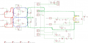
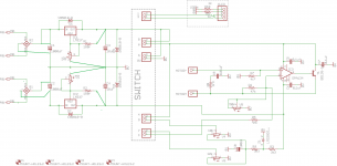
here is the schematic.
Of these layouts, I'd probably prefer version D.
I start with the current loops. These should be small, not overlap or use the same traces.
Do some sims if you are not sure what the currents look like.
Modify the schematic to fix the loops and any important connections like feedback or ground.
Now all you have to do is copy the schematic to layout.
Do some sims if you are not sure what the currents look like.
Modify the schematic to fix the loops and any important connections like feedback or ground.
Now all you have to do is copy the schematic to layout.
Attachments
> whats the reason for taking the 0V,GND from the smoothing caps instead of the rectifiers?
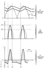
Rectifier current is BIG spikes. Like standing near the highway when a convoy of gravel trucks is going past. Or a 100Hz jack-hammer.
Smoothing cap voltage is (should be) smoother.
Treat the rectifier lines like garbage. Don't let them bleed toward your audio. Generally they should be short, direct, and not conjoined with the "good DC".
Also plagiarize. You are not the first to design such a thing. Study/steal the work of others.
Bibio, you can't think of the whole ground trace as being 0V.
My choices are based on analysis of the circuit. You have used LM317/LM337 regulators. The datasheet tells me that the maximum output current (Io) is 1.5A. I did some simulations and I see that the full wave current into C1 from the rectifiers is about 8 to 10 times higher than Io. This is the red current loop in the schematic. I need to prevent this really nasty looking current from interacting with any other parts of the circuit. To accomplish this, I run parallel traces from the AC input to the rectifier and then to the pins of C1. Even better if you can layout the return traces overlapping on the underside of the board.
The regulator adj input connects to a voltage divider (R1 and V1). Where you connect V1 becomes the reference voltage for the regulator. The regulator output will be a fixed voltage above this "0V". If the "0V" fluctuates because of current passing through it, the output will also do the same.
Attachments
Bibio, you can't think of the whole ground trace as being 0V.
My choices are based on analysis of the circuit. You have used LM317/LM337 regulators. The datasheet tells me that the maximum output current (Io) is 1.5A. I did some simulations and I see that the full wave current into C1 from the rectifiers is about 8 to 10 times higher than Io. This is the red current loop in the schematic. I need to prevent this really nasty looking current from interacting with any other parts of the circuit. To accomplish this, I run parallel traces from the AC input to the rectifier and then to the pins of C1. Even better if you can layout the return traces overlapping on the underside of the board.
**The regulator adj input connects to a voltage divider (R1 and V1). Where you connect V1 becomes the reference voltage for the regulator. The regulator output will be a fixed voltage above this "0V". If the "0V" fluctuates because of current passing through it, the output will also do the same.**
** your bang on the money there Mark.
yes i'm getting a small tick of voltage fluctuation but i put that down to measuring with a DMM. ''i really need a scope''
so what i'm best to do is move things around and get the input caps in the middle of the board, take the +- from the recs to the corresponding +- of the input caps and then create the 0V from there.
my reasoning was the 0V is return so no smoothing needed but i now know i'm wrong.
mad idea warning.. lol
if one were to place small lets say 0.1uF ceramic caps in place of the traces (or a break in the traces to place cap in as a bridge) from each of the rec +- before the input caps would this not smooth the pulses better?


Here are another three.
Version #1 seems better. Bear in mind that there are different viewpoints on pcb layout.
Think I'd move the two Vadj pots close to the gnd line, and then move C7 and C8 closer
to the regulator outputs.
Last edited:
Here are another three.
1:
View attachment 616904
2:
View attachment 616905
3:
View attachment 616906
am i getting close
i removed the bridge rectifiers to another board.
What I see is that the return current from load and some caps runs through a track back to the center tap and the bottom of the trimpot. Because that track is not zero ohms, you get a disturbing voltage between the load zero and the trimpot zero which means that the regulator tries to include the disturbing voltage on the output.
You must chose a reference point as 'zero' or 'ground' and refer everything to that point. The best point to refer the trimmer pot to is the point where the load gets returned, because you want the voltage at the load to be pure, not the voltage 'somewhere else'.
Jan
thank you.
i think i understand what both of you have said so i have moved the trimmer pots close to the 0V and also used separate 0V return trace to the smoothing caps dedicated to the trimmer pots. i have also bunched up the rest to get the output caps C7-8 closer to the regulator.

i'm still a bit confused as regards 'reference point'. the only way i can think of is taking C5,6,7,8 0V to C3,4 0V return as shown below.

i think i understand what both of you have said so i have moved the trimmer pots close to the 0V and also used separate 0V return trace to the smoothing caps dedicated to the trimmer pots. i have also bunched up the rest to get the output caps C7-8 closer to the regulator.
i'm still a bit confused as regards 'reference point'. the only way i can think of is taking C5,6,7,8 0V to C3,4 0V return as shown below.
In your post above, the lower figure, C3 and C4 are doing the same job as your main caps, C1, C2. Therefore I would move the ground point for C3 and C4 to the "bar" in between C1 and C2. The "bus bar" trace is where most current will be flowing back and forth, so you do not want to use that point as a "quiet" ground directly. Instead, make a short trace that leads away to another "star ground" point, where you can ground the caps for the regulators and other components that need a quiet(er) ground. The trace that connects the bar between C1 and C2 and the star ground does not need to be thick/wide, and probably should not be. It only needs to be wide enough to carry whatever current it will experience without problems. A thinner trace will have a small amount of resistance and inductance, and that will help to isolate it from the main cap bus bar. You sort of made a start ground point where you brought some traces together between the trimpots and large caps. I would move this farther away from the large caps. You might consider locating the start ground at the point where the existing ground trace meets the apex of the triangle that opens into the ground plane. This is IMO the concept behind the star-on-star grounding scheme, and I have seen this approach mentioned by Self and Cordell.
Last edited:
so like this,

BTW, this is not for audio. the whole circuit is essentially voltage control of a motor. i had other boards fabed prior to this design.
the problem i'm experiencing with my other test boards is the main regulation is randomly oscillating as far as i can see and this relates to an oscillation at the motor. basically as the voltage at the regulation goes up and down slightly the motor fluctuates along with it. the voltage might be stable for say 3 seconds then it will settle, i'll then get another 'spike' at another random interval.
with the regulation/power supply disconnected from the rest of the circuit (two separate boards) it does the same thing so i'm putting it down to the main power supply/regulation.
yes silly works me used a ground plane on the other circuit design for the power supply. hey its a learning curve
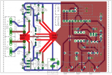
Why did you drag the ground plane way over to the left??? Remember, you want to put some distance between the "bus bar" between caps C1 and C2 and the star ground point. I would use the previous ground plane and instead route the ground wires over to the spot just where the ground trace leading from between C1 and C2 meet the ground plane. This is really where C7 and C8 should be "grounded" anyway, so you might as well move the star there. C7 and C8 can be thought of as a little power supply, and the return path to them from the components that they supply should not be any longer than it needs to be. Also, the trimpots should NOT be grounded between C1 and C2, they should connect into the quiet star ground point. It doesn't matter whether this is for audio or not, these principles help to keep noisy (carrying large currents) and quiet (carrying very little current) grounds "separated". Of course all grounds connect together electrically, but the traces that connect are what helps to "isolate" them.
See attached plot for what I mean... I made the connection between noisy and quiet ground thinner and re-routed traces. Not sure how much current needs to flow and where in your application, but this seems to be an improvement from what I know about your circuit, whether audio or not.
Also, if you want better filtering of the upstream supply you might consider using an RC or CRC on the incoming DC power or getting a better upstream supply. Maybe it is sending spikes on the DC?
Attachments
Last edited:
i dont know if this helps but i have checked the milliamp's on the boards i have here.
on startup with the motor connected i get around 180ma which drops rapidly to bouncing anywhere between 34ma to 41ma with no stable figure.
the above figures are taken between the output of the supply and the input of the circuit.
so we can say a max of 200ma for the supply.
on startup with the motor connected i get around 180ma which drops rapidly to bouncing anywhere between 34ma to 41ma with no stable figure.
the above figures are taken between the output of the supply and the input of the circuit.
so we can say a max of 200ma for the supply.
- Status
- This old topic is closed. If you want to reopen this topic, contact a moderator using the "Report Post" button.
- Home
- Amplifiers
- Power Supplies
- 0V, GND schemes