Do you mean secondary DC resistance? If so, calculate using knowledge of the wire used and length. Or measure it.
Do you mean effective secondary resistance? If so, calculate from measured primary and secondary resistance and voltage ratio. Or from measured voltage droop at a known current.
Secondary resistance is one of those things which if you know why you want the number then you know how to obtain the number.
> you know the output V, off load V, and I rating ?
Same as any Ohms Law problem.
Difference of Voltage, divided by Current.
Example: Rated 12V at 1 Amp, 15V at no load. 3V difference. Caused by 1A current. 3V/1A is 3 Ohms.
This is NOT the "secondary resistance", but the sum of primary and secondary resistances (and also leakage inductance). Which is usually what you really want to know: the total loss. How this splits between primary and secondary is usually only important to the transformer designer.
Last edited:
You can make some estimate of the secondary resistance from only the on-load output voltage and the open circuit output voltage. As above in PRR's post, the secondary resistance will normally be half of the resistance measured from the voltage drop. The other half is the transformed primary resistance (primary resistance divided by turns ratio squared).
Most of a transformer's voltage drop under load comes from leakage reactance due to imperfect coupling between pri/sec. That models as an equivalent series inductance, not resistance. The same laws of reflected impedance between pri and sec apply - it's just there's a "j" in there. Little bitty five watt trafos may be dominated by resistance, but anything you really want to make an amplifier with won't be. With really big power trafos they rate them in "% reactance" because the resistive part is vanishingly small.
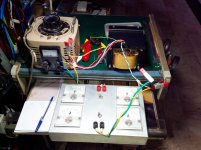
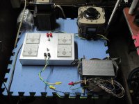
i do copper loss testing aka short circuit testing of my traffo builds....
i test them in increments of 1 amperes or up to rated primary current....
i use a variac and a home brew voltage and current meters...
the variac supplies low voltage to the primary, while all secondary windings are shorted together...
very straightforward to use, just read the voltage at the rated current...
this is a non destructive test.....
Attachments
> i do copper loss testing
Do you (or anybody) have data about wg_ski's statement "Most of a transformer's voltage drop under load comes from leakage reactance..."?
Reactance matters, why is why I edited it into my post.
At 10KVA and up it becomes dominant. (In part because of the economics of large power: resistance is real loss while reactance is just sag, and useful to limit fault current into a short.(
Below 1KVA, I would expect many transformers to have low reactance. However there are many ways to wind the little beasts. Primary over secondary is well coupled. Pri and Sec on separate legs is poor coupling, and often done for safety, shape, or to reduce HF noise.
X/R ratio is related to kVA in general. Maybe not linearly, but perhaps more exponentially. The IEEE Red Book has graphs of 'typical' X/R ratios, but this is pertinent specifically to transformers that rate in the MVA's.
Point being, small dry type transformers have X/R ratios around 1 at about 15 kVA three phase, and it climbs to approx 5 when you reach 1000 kVA. From there you tend to find a limit around 20-30 for the really big boys. Transformers that rate in VA are dominated by resistance, and this I have tested up to around 500 VA single phase. Anything in home audio will be mostly resistance, regardless if you are talking toroid or EI. Sure, EI will have more relative leakage, but it's still small in comparison to the resistance that contributes to overall impedance Z.
Point being, small dry type transformers have X/R ratios around 1 at about 15 kVA three phase, and it climbs to approx 5 when you reach 1000 kVA. From there you tend to find a limit around 20-30 for the really big boys. Transformers that rate in VA are dominated by resistance, and this I have tested up to around 500 VA single phase. Anything in home audio will be mostly resistance, regardless if you are talking toroid or EI. Sure, EI will have more relative leakage, but it's still small in comparison to the resistance that contributes to overall impedance Z.
> i do not know how to measure it....
I do not know the Golden Way to measure.
Cave-man: read output V with and without heavy resistor load, working normal input V and Hz. This gives a Total Impedance. Also get the Ratio. Now use DC techniques (low-range ohm meter) to read the windings. Add, adjusted for Ratio.
If it looks the same both ways, reactance is small.
As zigzag says, very large transformers will show sag on resistive load greater than can be accounted by R measured with DC. Mostly stray inductance. Some small part is skin effect (very small for large windings on 60Hz). There are other errors due to core loss. I have a fat undigestable book about meter transformers and their errors (big electric customers whine about 1% errors in metered billing because the cost is worth whining about, and big loads are metered via transformers).
My again-caveman impression is that below 1KVA the reactance is one of the smallest errors we face, that a resistive-load-sag test includes reactance to a good approximation, and we don't think about it. Above 1KVA it may matter, but above 1KVA we tend to go 2KVA for a 1.3KVA load so total series-loss is small in any case.
AH! All above for sine AC load. Now when you do Rectifiers, it isn't 60Hz. The rising edge of the diode turn-on throws harmonics above 1KHz. These are reduced by parasitic inductance, and the rise-time is slowed. I would think in most cases it would be hardly-slowed and would rise asymptotically toward the Peak before the wave turned around, but some added drop could happen.
The primary winding magnetising current will increase and may become noticeable (as an effectively lower primary winding voltage) as line voltage gets closer to max rated primary voltage.
Secondary winding voltage may effectively be a bit lower (for rectified and filtered secondary applications) if the line voltage waveform has typical flat spotting.
Some have come across small low power transformers that specifically incorporate substantial secondary leakage inductance - I recall as a current limiting requirement for certain (I think industrial) applications. Somebody may recall which post in the quasimodo threads.
Franciscano, was the query related to PSUD2 assessment, or something else?
Anything in home audio will be mostly resistance, regardless if you are talking toroid or EI.
thanks, this is all i need to know...
Cave-man: read output V with and without heavy resistor load, working normal input V and Hz. This gives a Total Impedance. Also get the Ratio. Now use DC techniques (low-range ohm meter) to read the windings. Add, adjusted for Ratio.
If it looks the same both ways, reactance is small.
thanks PRR, will try this sometime...
AH! All above for sine AC load. Now when you do Rectifiers, it isn't 60Hz. The rising edge of the diode turn-on throws harmonics above 1KHz. These are reduced by parasitic inductance, and the rise-time is slowed. I would think in most cases it would be hardly-slowed and would rise asymptotically toward the Peak before the wave turned around, but some added drop could happen.
yes, i am very much aware of this....one reason to build them stronger...
Thank you all for your answer.
I took the datasheet for a transformer, where all the information is already known. It is 400-0-400 at 0.4mA, DCR from ct to one side is ~31ohm. The offload voltage is about 425V.
So if i use the Ohm law on the voltage difference, it gives me a pretty close result. 25Vd / 0.4mA = 62.5 / 2 (for each side) = 31.25 ohm.
Tried this with other transformer, from datasheet 375-0-375v at 200mA, 397V unloaded, ~52ohm DCR from ct to one side. 22v / 0.2 = 110 / 2 = 55ohm.
I don't know if this is the right way to do it but it gets pretty close.
The reason I've asked, is because my power transformer DCR seams pretty low, ~25ohm from ct to one site. I wanted to know the difference between my pt and the original pt used in the schematic. Compensate with a high W resistors if needed, to limit the current, so the rectifier and caps wont explode") .
.
I took the datasheet for a transformer, where all the information is already known. It is 400-0-400 at 0.4mA, DCR from ct to one side is ~31ohm. The offload voltage is about 425V.
So if i use the Ohm law on the voltage difference, it gives me a pretty close result. 25Vd / 0.4mA = 62.5 / 2 (for each side) = 31.25 ohm.
Tried this with other transformer, from datasheet 375-0-375v at 200mA, 397V unloaded, ~52ohm DCR from ct to one side. 22v / 0.2 = 110 / 2 = 55ohm.
I don't know if this is the right way to do it but it gets pretty close.
The reason I've asked, is because my power transformer DCR seams pretty low, ~25ohm from ct to one site. I wanted to know the difference between my pt and the original pt used in the schematic. Compensate with a high W resistors if needed, to limit the current, so the rectifier and caps wont explode
.- Status
- This old topic is closed. If you want to reopen this topic, contact a moderator using the "Report Post" button.
- Home
- Amplifiers
- Power Supplies
- How to calculate transformer secondary resistance ?