Hi there,
Some times ago, Mark presented a little tester to determine the relative phases of a transformer's windings.
http://www.diyaudio.com/forums/powe...rmer-phasedots-no-scope-signal-generator.html
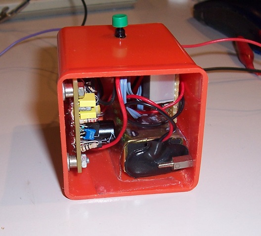
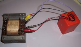
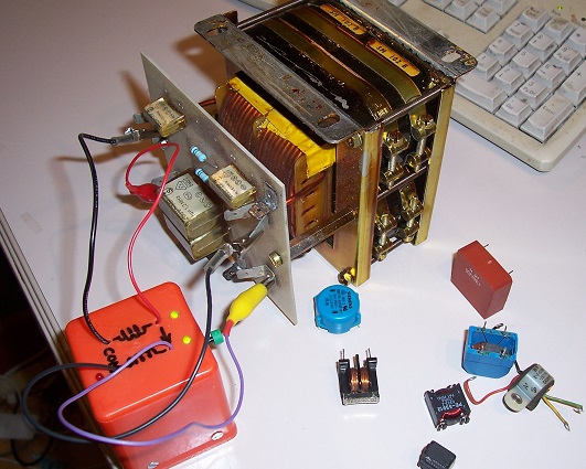
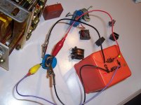
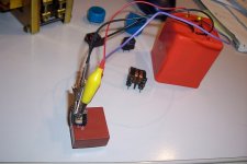
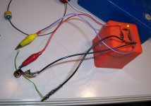
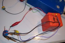
I thought it would be useful to extend its capabilities to wound components other than LF transformers, in essence make an "universal" tester for the DIYers: the "Orange Block":

Of course, nothing is "universal", which is the reason for the quotes, but modern DIYers are also confronted to SMPS transformers, gate drive transformers, common-mode chokes, and various types of coupled inductors, for which the phase generally matters, and an instrument capable of coping with all of that would cover most of the needs.
The basic principles I used are broadly the same as for Mark's version, but the details differ significantly:
The first important difference is the use of sinusoidal stimulus signal.
It is more complicated and difficult than a squarewave, but it has significant benefits: firstly, the absence of ringing, allowing an operating frequency of 1.25kHz without side-effects, even for large 50Hz transformers.
Secondly, differentiating effects do not alter the shape of a sinewave: they just affect the phaseshift which is manageable within limits, but a differentiated squarewave amplified and limited becomes quickly unusable.
Thirdly, the non-linearity and saturation effects of the core impacts more severely the integrity of a squarewave.
In addition, the amplitude of the stimulus is very low (~250mV rms), precisely to limit the effect of core saturation, and the drive impedance is low, to minimize differentiating effects stemming from the L/R time constant.
To further eliminate most parasitic effects, the reference signal is sampled directly across the winding under test.
Since the amplitudes are small, a very large amplification is required: XOR gates used in linear mode provide the necessary gain (~60dB).
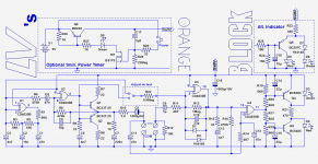
The schematic:

U1 is the master-oscillator, of the phaseshift variety, and the sine signal is picked at the input, after the filter network: there, the 1.25kHz signal has an amplitude of 600mVpp.
This signal passes through U2, playing the role of a -1 buffer, having a very low output impedance.
The gate is frequency-compensated by R5/C3, and the amplifier has a phase advance cap C6 and a Zobel network, just like any regular audio amp.
The Xover distortion is handled by the speed and the gain of U2, this is not actual audio after all.
The recovered signal at the tested winding is then amplified by U3, and limited by the diodes.
This signal and the reference taken from the primary are fed to U4, operating as a linear DBM more than a regular XOR: both inputs are precisely biased at the gate threshold voltage, thanks to the matching between the operators of the 4030.
Its output is a PWM signal proportional to the phase difference.
The indicator circuit lights the corresponding LED and blanks both LEDs for intermediate values.

...
To be continued....
Some times ago, Mark presented a little tester to determine the relative phases of a transformer's windings.
http://www.diyaudio.com/forums/powe...rmer-phasedots-no-scope-signal-generator.html
I thought it would be useful to extend its capabilities to wound components other than LF transformers, in essence make an "universal" tester for the DIYers: the "Orange Block":
Of course, nothing is "universal", which is the reason for the quotes, but modern DIYers are also confronted to SMPS transformers, gate drive transformers, common-mode chokes, and various types of coupled inductors, for which the phase generally matters, and an instrument capable of coping with all of that would cover most of the needs.
The basic principles I used are broadly the same as for Mark's version, but the details differ significantly:
The first important difference is the use of sinusoidal stimulus signal.
It is more complicated and difficult than a squarewave, but it has significant benefits: firstly, the absence of ringing, allowing an operating frequency of 1.25kHz without side-effects, even for large 50Hz transformers.
Secondly, differentiating effects do not alter the shape of a sinewave: they just affect the phaseshift which is manageable within limits, but a differentiated squarewave amplified and limited becomes quickly unusable.
Thirdly, the non-linearity and saturation effects of the core impacts more severely the integrity of a squarewave.
In addition, the amplitude of the stimulus is very low (~250mV rms), precisely to limit the effect of core saturation, and the drive impedance is low, to minimize differentiating effects stemming from the L/R time constant.
To further eliminate most parasitic effects, the reference signal is sampled directly across the winding under test.
Since the amplitudes are small, a very large amplification is required: XOR gates used in linear mode provide the necessary gain (~60dB).
The schematic:
U1 is the master-oscillator, of the phaseshift variety, and the sine signal is picked at the input, after the filter network: there, the 1.25kHz signal has an amplitude of 600mVpp.
This signal passes through U2, playing the role of a -1 buffer, having a very low output impedance.
The gate is frequency-compensated by R5/C3, and the amplifier has a phase advance cap C6 and a Zobel network, just like any regular audio amp.
The Xover distortion is handled by the speed and the gain of U2, this is not actual audio after all.
The recovered signal at the tested winding is then amplified by U3, and limited by the diodes.
This signal and the reference taken from the primary are fed to U4, operating as a linear DBM more than a regular XOR: both inputs are precisely biased at the gate threshold voltage, thanks to the matching between the operators of the 4030.
Its output is a PWM signal proportional to the phase difference.
The indicator circuit lights the corresponding LED and blanks both LEDs for intermediate values.
...
To be continued....
Attachments

Now, let us examine in more details what this tester can handle, and perhaps more importantly, what is off limits, but first a warning:
This tester is for DIY only: it relies on the properties of CMOS logic circuits used in linear mode, that is completely outside their normal operating envelope, and none of the key characteristics for this mode are specified: GBW product, gain, threshold, impedances, etc.
Serious designs should only rely on guaranteed min/max values, not on implicit properties.
The fact that the datasheets show linear applications is not an endorsement.
For a private use, such a use is legitimate, but you don't want your all business to critically depend on such evanescent properties.
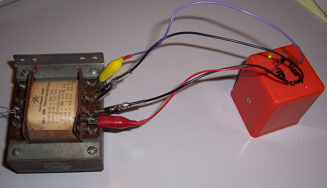
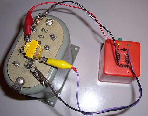
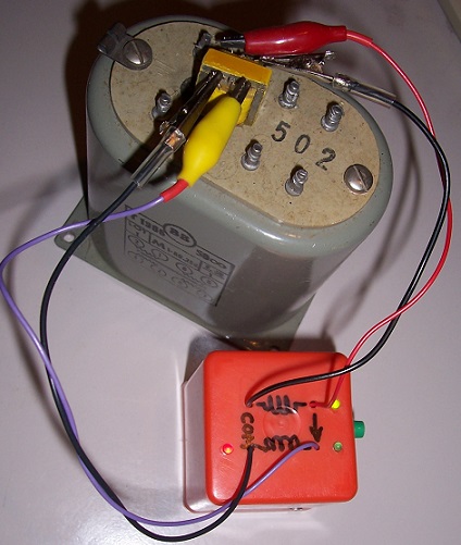
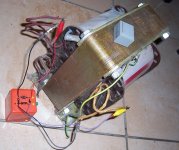
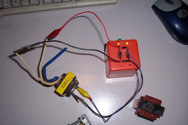
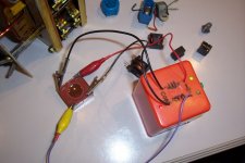
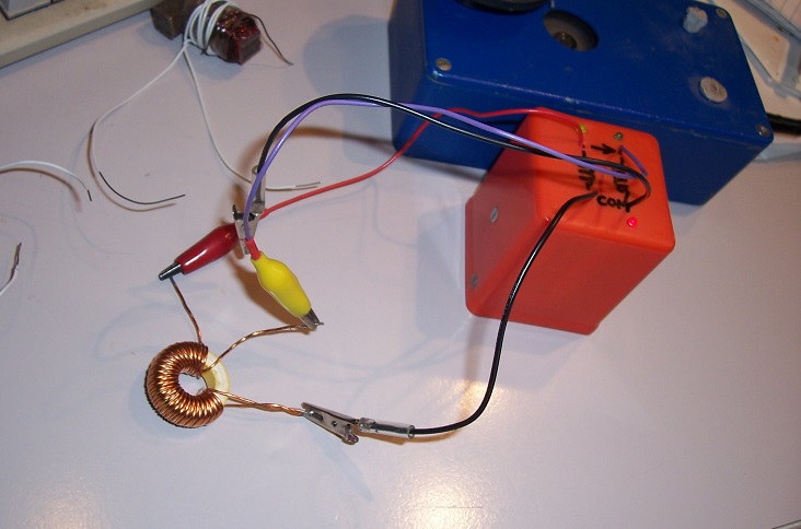
Let us begin the review with 50Hz power transformers: basically, it does them all, from tiny to huge, provided they are actual transformers (saturated iron voltage regulators, ballasted neon sign transformers, etc do not enter that category)

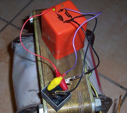
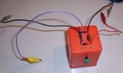
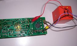
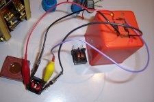
In-circuit testing is normally possible, thanks to the low impedance and low drive voltage:

For most power transformers, LF or SMPS, any winding can indifferently be used as the reference: the circuit has enough margin to cope with that.
Here for example, the 4V winding is used as a reference and the measurement is carried out on the 260V winding:
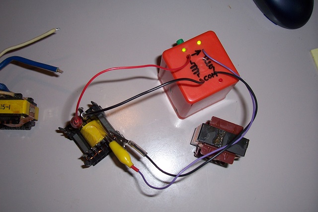
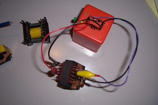
For higher frequency coils, that is not necessarily the case though.
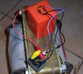
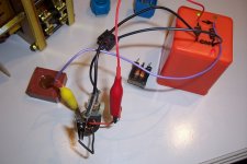
For large enough transformers, and if the copper window is sufficiently accessible, it is possible to determine the "absolute" winding direction, by passing a single turn:
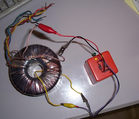
Note that the drive side cannot use a single turn
Audio transformers, big or small fall into the same category as 50/60Hz transformers:
To be continued....
This tester is for DIY only: it relies on the properties of CMOS logic circuits used in linear mode, that is completely outside their normal operating envelope, and none of the key characteristics for this mode are specified: GBW product, gain, threshold, impedances, etc.
Serious designs should only rely on guaranteed min/max values, not on implicit properties.
The fact that the datasheets show linear applications is not an endorsement.
For a private use, such a use is legitimate, but you don't want your all business to critically depend on such evanescent properties.
Let us begin the review with 50Hz power transformers: basically, it does them all, from tiny to huge, provided they are actual transformers (saturated iron voltage regulators, ballasted neon sign transformers, etc do not enter that category)
In-circuit testing is normally possible, thanks to the low impedance and low drive voltage:
For most power transformers, LF or SMPS, any winding can indifferently be used as the reference: the circuit has enough margin to cope with that.
Here for example, the 4V winding is used as a reference and the measurement is carried out on the 260V winding:
For higher frequency coils, that is not necessarily the case though.
For large enough transformers, and if the copper window is sufficiently accessible, it is possible to determine the "absolute" winding direction, by passing a single turn:
Note that the drive side cannot use a single turn
Audio transformers, big or small fall into the same category as 50/60Hz transformers:
To be continued....
Attachments

Most SMPS transformers are measurable too, provided they are "ordinary", for frequencies ranging from tens of kHz to hundreds of kHz. More exotic, multi-MHz types might be measurable in some cases, but that is less certain.


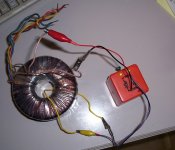
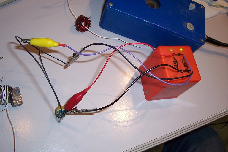
So far, we have seen actual transformers, but many other types of coupled components exist: common-mode chokes for example (CMC's).
They can perfectly be measured, provided their inductance is >50µH (the limit of the instrument), which is the case for lots of general purpose CMC's, large or small:


So far, we have seen actual transformers, but many other types of coupled components exist: common-mode chokes for example (CMC's).
They can perfectly be measured, provided their inductance is >50µH (the limit of the instrument), which is the case for lots of general purpose CMC's, large or small:
Attachments
-
 OrBlock22.jpg152.3 KB · Views: 218
 -
 OrBlock21.jpg159.8 KB · Views: 209
 -
 OrBlock20.jpg156.7 KB · Views: 219
 -
 OrBlock19.jpg196.4 KB · Views: 224
 -
 OrBlock18.jpg189.1 KB · Views: 213
 -
 OrBlock17.jpg117.3 KB · Views: 205
 -
 OrBlock16.jpg129.5 KB · Views: 213
 -
 OrBlock15.jpg124.6 KB · Views: 214
 -
 OrBlock14.jpg133 KB · Views: 210
 -
 OrBlock13.jpg140.6 KB · Views: 226
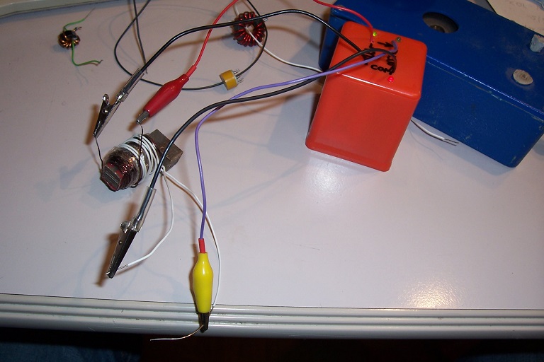
Now, let us see the result of more "informal" tests  :
:
First, a center-tapped iron powder coil:
Then a ferrite toroid

And an amorphous metal toroid

A current transformer
An open core is also OK
From here, things get really weird....

I wouldn't rely too much on that, but at least it does show the versatility of the thing....
I mentioned already a few exceptions, here are some more:
-anything having a too small magnetizing inductance: VHF UHF transformers, small air-core transformers....
-Transmission-line or cavity-based impedance transformers
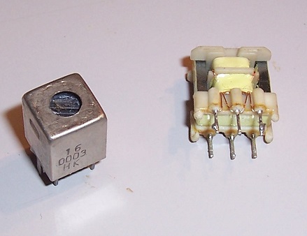
-IF transformers: this is a bit surprising, because they more than fulfill the inductance criterion, but they also have a significant series resistance and a tiny iron area, very susceptible to saturation.
The same goes for DSL filter inductors: their 68µH should suffice, but they have a significant DC resistance and a small effective area:
:First, a center-tapped iron powder coil:
Then a ferrite toroid
And an amorphous metal toroid
A current transformer
An open core is also OK
From here, things get really weird....
I wouldn't rely too much on that, but at least it does show the versatility of the thing....
I mentioned already a few exceptions, here are some more:
-anything having a too small magnetizing inductance: VHF UHF transformers, small air-core transformers....
-Transmission-line or cavity-based impedance transformers
-IF transformers: this is a bit surprising, because they more than fulfill the inductance criterion, but they also have a significant series resistance and a tiny iron area, very susceptible to saturation.
The same goes for DSL filter inductors: their 68µH should suffice, but they have a significant DC resistance and a small effective area:
Attachments


Some additional information
Since the 4030 is used in an "irregular" manner, there might be concerns about interchangeability.
I tested the circuit with all the brands of 4030 and 4070 (apart from the number, they seem completely identical) I could put my hands on, and it worked in all cases (which doesn't mean it always will...), but the performances differed: the best were Moto MC14xx series, and HEF/HCF series.
The worst was a recently-made Fairchild.
To accommodate chips from any source, the compensations have been made over-aggressive: for most types, a fourth of C5 and C6 value is adequate, R5 and R15 can be more than doubled, and C6 and C10 can also be reduced or completely dispensed with.
If the compensations are tailored more reasonably to the actual circuit used, an improvement in performance can be expected.
For the attribution of the pins/gates, I dumbly followed the numerical order, which is certainly not the optimum method: since crosstalk plays an important role in the performances, it should be possible to gain significant improvements by choosing deterministically the pins/gates roles, based on a microphotograph of the chip for example.
I did the exercise on other occasions, and it did pay, but here I didn't have the patience to do it, but if someone feels in a tweaking mood, it is certainly worth doing.
The drive level and output resistance are the result of a tradeoff: to avoid saturating delicate ferrite cores, the drive should be as small as possible, but then the capability to work with large ratios will be impaired: single turn detection for example. Initially, I had adopted a much more robust drive, and a very low resistor R10 (which is the reason for the largish C8), but it saturated most small HF cores.
The value and connection of R22 has to be adjusted on the finished instrument, to keep both LEDs in the off state with the input terminals shorted: the average value at the output of U4 should be ~V+/2.
It compensates for various crosstalk paths, and depends on the chip, layout and wiring.
I have shown an alternative indicator which always lights a LED: it potentially has more sensitivity because there is no "dead zone", but it might also have a potential for errors in borderline conditions.
The dead zone can be adjusted with the values of R19 and R18.
With the values shown, I never encountered a case of wrong (reversed) indication: the worst that has happened is an absence of indication.
Note that this is valid only if the tester is properly connected: if for example the two input terminals are connected to two different, mutually floating windings, the indication, if any, will be completely random, dependent on the interwinding parasitic capacitances.
It is thus a good idea to first make a proper test with an ohmmeter, for which this instrument is no substitute.
The power timer is optional: it came as an afterthought, after I realized that this tester had a great potential to become a battery-eater: that is typically the kind of thing I forget "on" every second time I use. If you feel more confident, you can adopt a traditional switch.
The supply could probably be improved: the PSRR of CMOS used in linear is typically only ~6dB, and I tackled the problem by brute force: a large C18.
A more clever approach would be to use two RC decoupling circuit, one for the power stage and one for the 4030.
No regulation is necessary, the tester operates easily from 3 to 10V.
There are probably other ICs that could be diverted into that function, perhaps more effectively than the 4030: PLL circuits come to mind, or special function ICs like horizontal combinations chips for TV: they contain an oscillator, one or two phase comparators, various support circuitry, and importantly a power stage which could eliminate two discrete transistors.
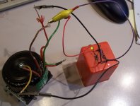
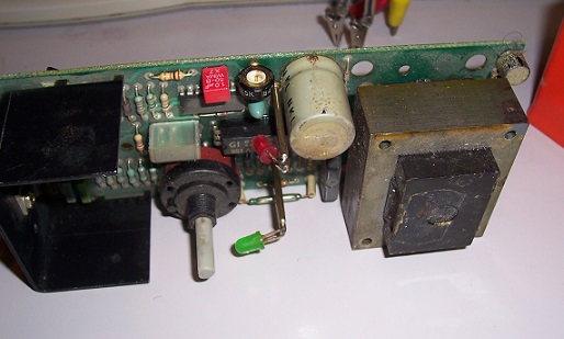
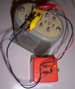
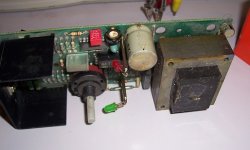
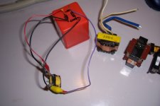
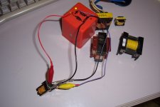
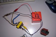
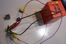
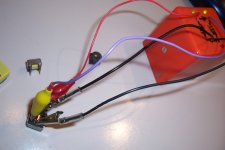
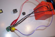
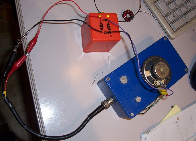
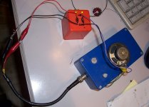
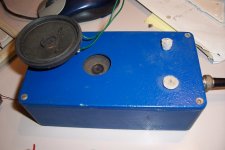
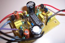
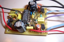
here some more pics of my prototype:
Since the 4030 is used in an "irregular" manner, there might be concerns about interchangeability.
I tested the circuit with all the brands of 4030 and 4070 (apart from the number, they seem completely identical) I could put my hands on, and it worked in all cases (which doesn't mean it always will...), but the performances differed: the best were Moto MC14xx series, and HEF/HCF series.
The worst was a recently-made Fairchild.
To accommodate chips from any source, the compensations have been made over-aggressive: for most types, a fourth of C5 and C6 value is adequate, R5 and R15 can be more than doubled, and C6 and C10 can also be reduced or completely dispensed with.
If the compensations are tailored more reasonably to the actual circuit used, an improvement in performance can be expected.
For the attribution of the pins/gates, I dumbly followed the numerical order, which is certainly not the optimum method: since crosstalk plays an important role in the performances, it should be possible to gain significant improvements by choosing deterministically the pins/gates roles, based on a microphotograph of the chip for example.
I did the exercise on other occasions, and it did pay, but here I didn't have the patience to do it, but if someone feels in a tweaking mood, it is certainly worth doing.
The drive level and output resistance are the result of a tradeoff: to avoid saturating delicate ferrite cores, the drive should be as small as possible, but then the capability to work with large ratios will be impaired: single turn detection for example. Initially, I had adopted a much more robust drive, and a very low resistor R10 (which is the reason for the largish C8), but it saturated most small HF cores.
The value and connection of R22 has to be adjusted on the finished instrument, to keep both LEDs in the off state with the input terminals shorted: the average value at the output of U4 should be ~V+/2.
It compensates for various crosstalk paths, and depends on the chip, layout and wiring.
I have shown an alternative indicator which always lights a LED: it potentially has more sensitivity because there is no "dead zone", but it might also have a potential for errors in borderline conditions.
The dead zone can be adjusted with the values of R19 and R18.
With the values shown, I never encountered a case of wrong (reversed) indication: the worst that has happened is an absence of indication.
Note that this is valid only if the tester is properly connected: if for example the two input terminals are connected to two different, mutually floating windings, the indication, if any, will be completely random, dependent on the interwinding parasitic capacitances.
It is thus a good idea to first make a proper test with an ohmmeter, for which this instrument is no substitute.
The power timer is optional: it came as an afterthought, after I realized that this tester had a great potential to become a battery-eater: that is typically the kind of thing I forget "on" every second time I use. If you feel more confident, you can adopt a traditional switch.
The supply could probably be improved: the PSRR of CMOS used in linear is typically only ~6dB, and I tackled the problem by brute force: a large C18.
A more clever approach would be to use two RC decoupling circuit, one for the power stage and one for the 4030.
No regulation is necessary, the tester operates easily from 3 to 10V.
There are probably other ICs that could be diverted into that function, perhaps more effectively than the 4030: PLL circuits come to mind, or special function ICs like horizontal combinations chips for TV: they contain an oscillator, one or two phase comparators, various support circuitry, and importantly a power stage which could eliminate two discrete transistors.
here some more pics of my prototype:
Attachments
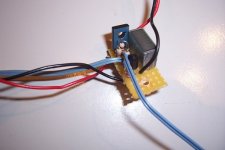
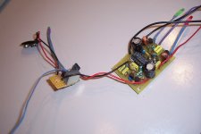
I would love to, but I don't have any: as you can probably see from the pics, it was built on perfboard, and I didn't even make a plan: I just improvised the layout as I went along, as I often do for simple or non-critical circuits.Would you like to share your PCB layout?
Note however that in this case, one should not be too sloppy: this is not logic, the sensitivity of the detector is less than 400µV, and the PSRR of the IC is awful, but if you are used to sensitive audio circuits like mike or RIAA preamps, this should be an easy task.
I would love to, but I don't have any: as you can probably see from the pics, it was built on perfboard...
Oh well, should get me some new glasses...
Best regards!
I am thinking about going in the opposite direction: 8 pin microcontroller IC + fancy software + practically no hardware. Variable frequency, variable amplitude autoranging in software. Phase detection in software.
Great idea to try an IF transformer from a superheterodyne radio!
Great idea to try an IF transformer from a superheterodyne radio!
- Status
- This old topic is closed. If you want to reopen this topic, contact a moderator using the "Report Post" button.
- Home
- Amplifiers
- Power Supplies
- My take on the winding's phase-finder (AKA "Phasedots tester")