max voltage power for Kali Reclocker?
Hi cdsgames, I am the happy owner of a Kali Reclocker (with RPI2 and DAC) and want to give it the best food!")
I have a 6 volt lead acid battery (agm), fresh loaded 6,4 volt.
With a buck converter from 6,4 to 5 volt it works, but it creates new noise
Can the Reclocker handle more than 5 volt?
What is the max?
Hi cdsgames, I am the happy owner of a Kali Reclocker (with RPI2 and DAC) and want to give it the best food!
I have a 6 volt lead acid battery (agm), fresh loaded 6,4 volt.
With a buck converter from 6,4 to 5 volt it works, but it creates new noise
Can the Reclocker handle more than 5 volt?
What is the max?

@cdsgames: These specs are phenomenally good!!
If you can also provide screw terminals for Vout, it will be possible for DIYers to mount the PS inside the cabinet and use shorter DC cables. (Though I wonder if there will be increased noise due to EM affecting the TPA3255 board!).
I am currently using a RPi with Allo Boss DAC HAT (older verseion) and a 7 in lcd. Power is fed thru the RPI to the DAC and by USB from the RPi to the Lcd using an IFI 5V adapter. The yellow power symbol keeps coming on indicating that the voltage to the RPi is low. Is it because the setup needs more current than 2.5A the IFI provides? Can you test your unit for this setup please.
Last edited:
I just learned that you've upgraded your boards (at least the Boss I heard of) in the power area.
Which (hopefully) would now allow to combine them or run them separately. And I'd hope to see the same consistent powering scheme over all your board offerings.
Can you confirm related updates for the other boards - Kali/Piano(2.1) - as well ??
And you also introduced (are introducing!?!?) a jumper (no more soldering, cutting traces or similar) to accomplish the separation of power rails between the boards.
To finally allow any combination of powering in a convenient fashion. Can you confirm this too??
Ah. The cream of the cake for the DIY crowd: Have you introduced soldering joints to solder power cables right to the board?
If so - to all above. Great.
We've been discussing it since quite some time and more than once.
However.
I also learned that e.g. the most recent Boss (a new board revision 1.4 or similar) comes now with USB-C ports!?!?
USB-C??
USB-C is not what I'd call standard in this area!!!!
Will you force us to switch all our power supplies and cabling!?!?
Now we'd be facing mixes of uUSB and USB-C on our PI towers!!!
You can't be serious about this !?!?
I guess your new 5V supply will then also come with USB-C !?!?
Last edited:
Is there a need to go that high in current delivery? If the Pi is powered separately to the hat dac or transport, only the hat(s) require the high quality low noise psu. The Pi can be powered by a standard smps ( Allo 3A unit). Will you be grounding the power supply to avoid leakage current noise issues (SMPS and grounding - UpTone Audio (Sponsored) - Computer Audiophile ) ?
Taming the beast.. different values for RC snubbers to quiet the emi and noise/ripple of the last diode (output side)
There is a significant difference between 1nf and 20nf *and much more whiteout any RC snubber)
I have copied your .pdf files into this post and I will be bold and suggest you seem to be looking in the wrong direction.
Your cursors, C1 and C2, have been set to measure what is in fact the primary inductance of your transformer ringing with the primary side switch capacitance during the primary side switch off time....
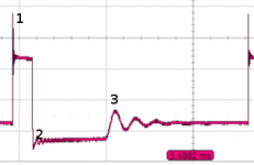
Look at the added picture.
1) Occurs when the primary side switch is on and your secondary diode is reverse biased. This is secondary side leakage inductance ringing with the reverse biased capacitance of the diode.
2) Occurs when the primary side switch first turns off and your diode conducts. This is primary side leakage inductance ringing with the primary side switch drain source capacitance in its off state.
3) Occurs when the secondary side diode stops conducting and the primary side switch is off. This is the primary side switch drain source capacitance in its off state ringing with the the primary side inductance.
Using RC snubbers you can 'kill' 1) and 2) but, whilst it might be reduced, 3) is always going to be present.
I am guessing that you are using a single switch flyback converter.
More words here...
LCRs / Ferrite beads between cascaded regulators?
LCRs / Ferrite beads between cascaded regulators?
LCRs / Ferrite beads between cascaded regulators?
Take note of the last link where there is a suggestion as to how you might determine the nominally ideal values for R and C in your RC snubbers and the second one which links to a web page that explains what is happening in a Forward converter...
Snubbing The Forward Converter
Sorry about this but in respect of "Best 5V SMPS" you appear to be missing simple knowledge of the basics. You do not arbitrarily slap 1nF or 20nF capacitors across diodes and then measure their minimal effect on the wrong resonance.
Attachments
Last edited:
Hi Morbid,
while I am not the lead engineer for the SMPS, I do know that our team tested (measured) the parasitic inductance of the transformer and calculated first RDC values (including the power dissipation of the R). In fact we chose a r2dc config for obvious reasons .
The RC across the mosfet was added as an extra protection and also to reduce HF noise at the turn on of the mosfet. Not sure how they calculated the RC snubber on the last diode. The captures you are referring are very old and not representative of what we are doing presently
At last we found the reducing the loop on the mosfet drain/source / Cin to a few square (dozens) mm and reducing the loop on the output (diode + Cout) + using a 4 layer PCB gave by far the best result in reducing the noise.
We also took care of the mosfet gate loop (usually forgotten) and we are not mixing the dirty ground to clean one (I mean we keep them separate and chose where to connect them using Vias)
Let me go further...we are using RC snubbers on the bridge rectifiers (all 4 Ds) along with 2 CMCs (input has 2 X capacitors , before and after) and one CMC on the output.. while using Y capacitors (we found SMTs..) strategically placed below transformer with direct line of sight ( no 90deg)
Sounds better ?
Last edited:
I have tried the Allo adapter, the IF I adapter, and a 10000mAh Battery bank from MI, for powering the RPI + BossDac. .
I get the best sound when I use the third one !!
It seems that no amount of filtering and cleaning AC can work better than a pure DC source.
On a practical side, charging a battery bank everytime may be a pain, but the pleasure that you get from the pristine pure sound, clear notes and deep bass makes it pale in comparison.
With the iFi power supply you need to connect the outer barrel of the DC connector to ground(earth pin at same AC outlet socket) to remove high impedance noise; [SMPS and grounding - UpTone Audio (Sponsored) - Computer Audiophile ]. When I did this the sound quality improved vs. the standard Allo 3A smps, before grounding sound was "smeared". Alternatively you can purchase a grounding connector from iFi Audio. it is similar to their groundhog kit in use.
is a powerbank pure DC?
I think a powerbank is not real clear DC... mostly there is a kind of buck converter to power up the 3,6 voltage of the lipo to 5 volt.
So I think there wil always be an amount of ripple and noise.
I have tried the Allo adapter, the IF I adapter, and a 10000mAh Battery bank from MI, for powering the RPI + BossDac. .
I get the best sound when I use the third one !!
It seems that no amount of filtering and cleaning AC can work better than a pure DC source.
On a practical side, charging a battery bank everytime may be a pain, but the pleasure that you get from the pristine pure sound, clear notes and deep bass makes it pale in comparison.
I think a powerbank is not real clear DC... mostly there is a kind of buck converter to power up the 3,6 voltage of the lipo to 5 volt.
So I think there wil always be an amount of ripple and noise.
It is rather interesting findings on Allo adapter, the IF I adapter, and a 10000mAh Battery bank from MI.
No doubt that AC power supply such as Allo, IFI comes with inherit noise. But pesonally, i always have doubt battery bank such as 10000mAh Battery bank from MI are noise-free; although they are from DC power supply, however 3.7~42v Li-battery undergo switching mode DC-DC to bring up to 5v USB power, such approach inherently cause switching noise output as well.
No doubt that AC power supply such as Allo, IFI comes with inherit noise. But pesonally, i always have doubt battery bank such as 10000mAh Battery bank from MI are noise-free; although they are from DC power supply, however 3.7~42v Li-battery undergo switching mode DC-DC to bring up to 5v USB power, such approach inherently cause switching noise output as well.
- Status
- This old topic is closed. If you want to reopen this topic, contact a moderator using the "Report Post" button.
- Home
- Amplifiers
- Power Supplies
- Best 5V SMPS ?