Hello;
I want to build an amplifier which includes 2 amplifier instead;
For Pass F5 and JLH2003, but want to use same power supply for both. -+22v.
JLH2003

F5
1.3A bias 40W 4ohm 25W 8ohm as far as i know.
But i do not know how much amp they draw i think it is important to calculate voltage raiting in troidal.
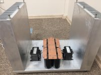
I do not have any knowledge about electronic but i am good at mechanical things. So i build a case i alittle bit overkill i guess but nevermind my problem is define the secondary voltage troidal transformer according to setup here below;
Input/primary is 220v 50hz
I will use soft start
i will use CLC setup.
Rectifier: 2X IXYS VBE17-06NO7
Capacitor 8x Sikorel B41570E7479Q
Choke: 2X 195J10
Troidal will be 1500VA (750VA for each channel) %4-5 regulation probably.
So;
Can anybody tell me is there something wrong in my setup to run both amplifier with same PSU and what will be the voltage in troidal transformer
I want to build an amplifier which includes 2 amplifier instead;
For Pass F5 and JLH2003, but want to use same power supply for both. -+22v.
JLH2003
F5
1.3A bias 40W 4ohm 25W 8ohm as far as i know.
But i do not know how much amp they draw i think it is important to calculate voltage raiting in troidal.
I do not have any knowledge about electronic but i am good at mechanical things. So i build a case i alittle bit overkill i guess but nevermind my problem is define the secondary voltage troidal transformer according to setup here below;
Input/primary is 220v 50hz
I will use soft start
i will use CLC setup.
Rectifier: 2X IXYS VBE17-06NO7
Capacitor 8x Sikorel B41570E7479Q
Choke: 2X 195J10
Troidal will be 1500VA (750VA for each channel) %4-5 regulation probably.
So;
Can anybody tell me is there something wrong in my setup to run both amplifier with same PSU and what will be the voltage in troidal transformer
Attachments

Sorry if my question is annoyying;
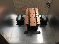
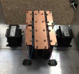
1)Do you want me to open a new screw hole in the middle of copper ground (red marked in IMG_2999.jpg picture) or want me to collect other grounds to blue square. Please my stetch in attachments.
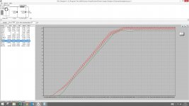
2)I try to make simulation with my poor knowledge as see in attachments adsiz.jpg;
If amplifier draw 10A and input is 18V my output seems 19.4V is this normal?
1)Do you want me to open a new screw hole in the middle of copper ground (red marked in IMG_2999.jpg picture) or want me to collect other grounds to blue square. Please my stetch in attachments.
2)I try to make simulation with my poor knowledge as see in attachments adsiz.jpg;
If amplifier draw 10A and input is 18V my output seems 19.4V is this normal?
Attachments
Last edited:
Do not make an extra connection in the middle of that zero volts plate.Sorry if my question is annoyying;
1)Do you want me to open a new screw hole in the middle of copper ground (red marked in IMG_2999.jpg picture) or want me to collect other grounds to blue square. Please my stetch in attachments.
2)I try to make simulation with my poor knowledge as see in attachments adsiz.jpg;
If amplifier draw 10A and input is 18V my output seems 19.4V is this normal?
Power from the transformer/rectifier comes in at one END. Power leaves to feed the amplifier from the other END.
You can make the Safety Connection to Chassis from this plate, but this could be from many other wires/cables in the assembly.
No other connections are made to the zero volts plate. Just the input and the output at opposite ENDs.
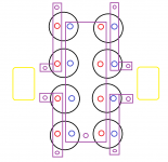
ZenMod's drawing in post6 seems to show different.
Get him to explain why his drawing will not put Hum and Buzz into the amplifier cabling.
Last edited:
Any news Andrew
Is there any news Andrew. Thanks in advance.
I can certainly draw it.
I have just borrowed a camera and could post a pic, if it can download to my PC.
Maybe later tonight.
Is there any news Andrew. Thanks in advance.
Hello;
I want to build an amplifier which includes 2 amplifier instead;
For Pass F5 and JLH2003, but want to use same power supply for both. -+22v.
JLH2003
View attachment 591513
F5
1.3A bias 40W 4ohm 25W 8ohm as far as i know.
But i do not know how much amp they draw i think it is important to calculate voltage raiting in troidal.
I do not have any knowledge about electronic but i am good at mechanical things. So i build a case i alittle bit overkill i guess but nevermind my problem is define the secondary voltage troidal transformer according to setup here below;
Input/primary is 220v 50hz
I will use soft start
i will use CLC setup.
Rectifier: 2X IXYS VBE17-06NO7
Capacitor 8x Sikorel B41570E7479Q
Choke: 2X 195J10
Troidal will be 1500VA (750VA for each channel) %4-5 regulation probably.
So;
Can anybody tell me is there something wrong in my setup to run both amplifier with same PSU and what will be the voltage in troidal transformer
wow... that's a kick *** psu, 1500va ... wow ... why you decided to go so big on the psu?
I'm planning to build a f5 and I was thinking a crc with 300va trans ... may be some more capacitance that recommend...
Not yet.
It is warming up a lot and I am going up on the roof to erect my new TV aerial. 1°C yesterday and 9°C today and enough daylight left to finish the job.
any news Andrew
")
- Status
- This old topic is closed. If you want to reopen this topic, contact a moderator using the "Report Post" button.
- Home
- Amplifiers
- Power Supplies
- Power supply for JLH2003 & F5 Amplifier