Hi there,
Yet another soft-start/anti-inrush circuit? Yes, but this one is different:
Usually, the soft-start circuit is an integral part of the appliance it protects, and uses signals, supplies and controls from its target.
This one is designed to be completely independent and autonomous, a black box you insert between the mains and the target.
This sounds like a counter-productive approach, so why did I develop it?
The integral approach is certainly the best one when you design everything from scratch, but when you need to retrofit an otherwise perfectly functional piece of equipment, the idea of meddling with its innards looks immediately less appealing: so many things can go wrong, you have to find spare space inside, etc.
That is true even for something you designed and built yourself: specifically, this circuit was developed for my lab isolated supply: it uses a special design 2.8kVA isolation transformer, a 1kVA autoformer, remote control circuits and meters.
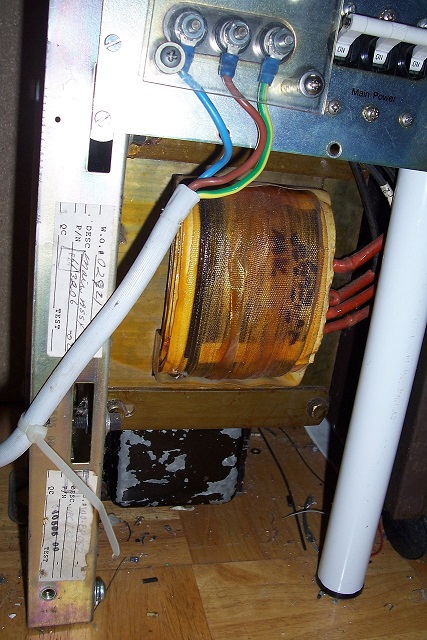
The transformer is very generously designed, and I never had inrush issues before, but two new elements came into play: my lab was moved to a former bedroom where the circuit-breaker is only 20A (it was 25A before), and the mains voltage has progressively migrated from 220V to 230V in continental Europe.
These are minor changes, but they were sufficient to pass a threshold: now, once or twice a year, when I power the system, it causes the breaker to trip.
It is very unfrequent, but nevertheless annoying enough: finding oneself in the dark (it happens at night, of course) with unsaved data on the PC is not pleasant, which is why I decided myself to build this circuit.
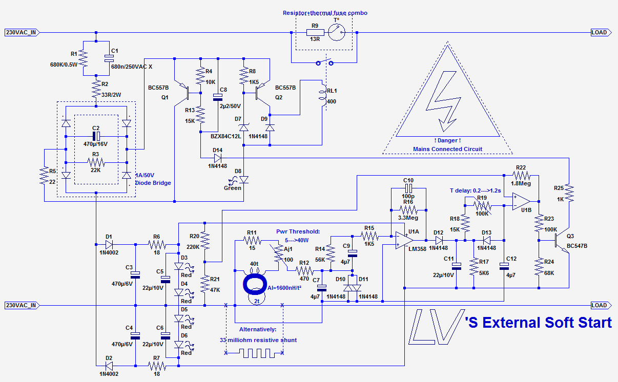
The principle is rather straightforward, and is common to many soft-starts: when the power is applied, the load is initially fed through a resistor, 13 ohm here, and after a few hundred ms, a relay closes and shorts the resistor away.
Here, the main difference is that the timing is started by the detection of current consumption (with an adjustable threshold, to allow for standby modes).
It looks more complicated than it needs to be, but it has been designed with two main objectives: minimize the power wasted both in standby and active modes, and offer a bullet-proof reliability, even when not used the way it is intended, or in the presence of an erratic mains supply.
The circuit is powered by two capacitive supplies, connected in series: one with the diode bridge takes care of the relay, and the other is symetrical and feeds the rest of the electronics.
When the relay is inactive, its supply is shorted, to minimize standby losses.
The current detection uses either a conventional shunt resistor, or a current transformer operating in very degenerated mode, where the magnetizing inductance plays the role of the shunt.
This solution is a bit more more complex, but it is preferable in view of the near-zero power lost.
When a current is detected, U1A goes into clipping and starts the timing period set by R19/C12. U1B acts as a comparator, and controls the relay via two transistors.
The relay could have been directly connected to the supply, but this has two inconvenients: the relay steals current for all the charging period of C2, adding to the delay, and the rise of the voltage is relatively slow, something I don't like, especially for a relay that has to handle tens of amperes.
Q2 and D7 provide a snap action when 12V is reached.
I used a 12V relay, because that was what I had at hand, but a higher voltage, 24 or 48V would be advantageous: the capacitive supply could be made smaller.
Some oddities still need explaining: the circuit also has to behave gracefully when it is already connected to the equipement and the power is applied: this could happen after a power cut for example.
In those circumstances, the soft-start must adopt the same behavior than when operated the normal way.
This means that it has to wake up deterministically, which is not so obvious to achieve.
R3 provides a discharge path for C2, because the wiring can be capacitively coupled to 50Hz, building up voltage until the zener threshold is reached, and such a voltage intereferes with the timing.
This kind of problem sometimes manifests itself with CFL lamps: an normally off lamp sometimes flashes periodically as it attempts to start on stray capacitive currents.
R14 provides a deterministic discharge path for C9 without increasing too much the DC gain, to avoid a recovery period at startup.
It is also the reason for the symetrical supply: the amplifier is almost instantly ready.
The whole of the circuit is live, and has to be enclosed in an insulating case.
The good news is that there is no coexistence with any other circuit: no optocoupler, transformer or relay. This eases considerably the safety aspects.
The 680nF capacitor C1 must imperatively be of an X variety (1, 2 or 3).
The relay has to be generously rated, and the 13 ohm resistor (value is not critical) must be capable of withstanding the power-on surge.
It has to be fitted with a thermal cutout, preferably integral, or external.
Do not attempt to make live measurements on the circuit, unless you have a suitable isolation transformer.
Yet another soft-start/anti-inrush circuit? Yes, but this one is different:
Usually, the soft-start circuit is an integral part of the appliance it protects, and uses signals, supplies and controls from its target.
This one is designed to be completely independent and autonomous, a black box you insert between the mains and the target.
This sounds like a counter-productive approach, so why did I develop it?
The integral approach is certainly the best one when you design everything from scratch, but when you need to retrofit an otherwise perfectly functional piece of equipment, the idea of meddling with its innards looks immediately less appealing: so many things can go wrong, you have to find spare space inside, etc.
That is true even for something you designed and built yourself: specifically, this circuit was developed for my lab isolated supply: it uses a special design 2.8kVA isolation transformer, a 1kVA autoformer, remote control circuits and meters.
The transformer is very generously designed, and I never had inrush issues before, but two new elements came into play: my lab was moved to a former bedroom where the circuit-breaker is only 20A (it was 25A before), and the mains voltage has progressively migrated from 220V to 230V in continental Europe.
These are minor changes, but they were sufficient to pass a threshold: now, once or twice a year, when I power the system, it causes the breaker to trip.
It is very unfrequent, but nevertheless annoying enough: finding oneself in the dark (it happens at night, of course) with unsaved data on the PC is not pleasant, which is why I decided myself to build this circuit.
The principle is rather straightforward, and is common to many soft-starts: when the power is applied, the load is initially fed through a resistor, 13 ohm here, and after a few hundred ms, a relay closes and shorts the resistor away.
Here, the main difference is that the timing is started by the detection of current consumption (with an adjustable threshold, to allow for standby modes).
- The circuit:
It looks more complicated than it needs to be, but it has been designed with two main objectives: minimize the power wasted both in standby and active modes, and offer a bullet-proof reliability, even when not used the way it is intended, or in the presence of an erratic mains supply.
The circuit is powered by two capacitive supplies, connected in series: one with the diode bridge takes care of the relay, and the other is symetrical and feeds the rest of the electronics.
When the relay is inactive, its supply is shorted, to minimize standby losses.
The current detection uses either a conventional shunt resistor, or a current transformer operating in very degenerated mode, where the magnetizing inductance plays the role of the shunt.
This solution is a bit more more complex, but it is preferable in view of the near-zero power lost.
When a current is detected, U1A goes into clipping and starts the timing period set by R19/C12. U1B acts as a comparator, and controls the relay via two transistors.
The relay could have been directly connected to the supply, but this has two inconvenients: the relay steals current for all the charging period of C2, adding to the delay, and the rise of the voltage is relatively slow, something I don't like, especially for a relay that has to handle tens of amperes.
Q2 and D7 provide a snap action when 12V is reached.
I used a 12V relay, because that was what I had at hand, but a higher voltage, 24 or 48V would be advantageous: the capacitive supply could be made smaller.
Some oddities still need explaining: the circuit also has to behave gracefully when it is already connected to the equipement and the power is applied: this could happen after a power cut for example.
In those circumstances, the soft-start must adopt the same behavior than when operated the normal way.
This means that it has to wake up deterministically, which is not so obvious to achieve.
R3 provides a discharge path for C2, because the wiring can be capacitively coupled to 50Hz, building up voltage until the zener threshold is reached, and such a voltage intereferes with the timing.
This kind of problem sometimes manifests itself with CFL lamps: an normally off lamp sometimes flashes periodically as it attempts to start on stray capacitive currents.
R14 provides a deterministic discharge path for C9 without increasing too much the DC gain, to avoid a recovery period at startup.
It is also the reason for the symetrical supply: the amplifier is almost instantly ready.
- Precautions
The whole of the circuit is live, and has to be enclosed in an insulating case.
The good news is that there is no coexistence with any other circuit: no optocoupler, transformer or relay. This eases considerably the safety aspects.
The 680nF capacitor C1 must imperatively be of an X variety (1, 2 or 3).
The relay has to be generously rated, and the 13 ohm resistor (value is not critical) must be capable of withstanding the power-on surge.
It has to be fitted with a thermal cutout, preferably integral, or external.
Do not attempt to make live measurements on the circuit, unless you have a suitable isolation transformer.
Attachments


Sorry but ... Surely this is just a resistive start with a timer working the relay contact. Why not use an RC network with a solid state relay?
Far cheaper, less to go wrong and only four components.
Far cheaper, less to go wrong and only four components.
Sure, that's the very well known internal soft start method, but how do you adapt it to sense that the connected device has shifted from standby to active (without an access to an auxiliary contact of the power switch)?Sorry but ... Surely this is just a resistive start with a timer working the relay contact. Why not use an RC network with a solid state relay?
Far cheaper, less to go wrong and only four components.
BTW, a solid state relay passing 15A has to dissipate ~15W, meaning a commensurate heatsink, not that cheap.
Since some clarifications seem necessary, here are the various options for retrofitting a soft-start.
Note that this solution (3), although designed for operation with the power-switch located downstream will also function with an upstream switch.
It can also be used to "secure" an outlet: it can be left connected permanently, and everything that is plugged-in will automatically be soft-started.
If you really think you can achieve the same functionality with just four components, feel free to share your solution.
A very crude substitute can be made with just one component: a NTC, but the drawbacks and limitations are well-known
A word about wasted power: it is ~800mW when active, and 250mW when idle
Attachments

Last edited:
- Status
- Not open for further replies.