I am going slightly mad over a bit of 100Hz hum (ripple, not 50Hz harmonic; there are no 50Hz transformer etc problems) I have in my tube mic preamp. Crazy not because I can hear it when recording, but because it seems to be random/intermittent on test software.
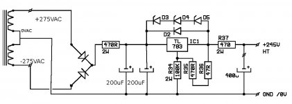
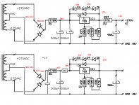
The HT psu is attached. Originally it had two 200uF caps and the hum was pinned to about -65db on medium gain when acting up and down to -75 when doing fine.
I then bought a 400uf poly(!) for the second cap and bundled the old ones together for the first. Hum went down to -78 when acting up, or to about -90 (pretty much at general tube noise level on all but the lowest gain)
What drives me mad is why is it intermittent. At all times my DMM shows 0.000 AC on both caps. The grounding seems sound. I've tried a few different ground schemes and mods with no effect.
For a couple days I left the amp under constant 1K sine and looked from time to time at the 100Hz bump. It can be there for a few hours then it goes away for a while then back again. There is nothing in the house that can be associated with the change. There are times when it looks good and everything else draws current: computer nearby, lights, fridge, TVs everything. It is not software error or soundcard interference as my other preamps do not do it.
I am suspecting something odd coming from the mains. Or something fishy within the regulator. Or perhaps this is just about the best this particular reservoir size can do. Can't really up it any more for space reasons, the 400uf poly is the size of a milk bottle.
Would adding a very small value resistor in between the parallel first two caps improve it a bit? Or perhaps split them- move one *before* the first resistor?
Again, at -78db I can't hear it in recordings but I can't get over it. The overall noise level of the amp is excellent and pretty much on par with 3 other solid state pres I have.
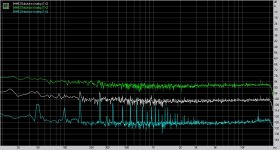
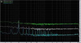
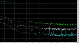
Attaching noise plots at 20, 40 and 55db of gain, when it is not acting and then when it is acting up.
Thanks!!
The HT psu is attached. Originally it had two 200uF caps and the hum was pinned to about -65db on medium gain when acting up and down to -75 when doing fine.
I then bought a 400uf poly(!) for the second cap and bundled the old ones together for the first. Hum went down to -78 when acting up, or to about -90 (pretty much at general tube noise level on all but the lowest gain)
What drives me mad is why is it intermittent. At all times my DMM shows 0.000 AC on both caps. The grounding seems sound. I've tried a few different ground schemes and mods with no effect.
For a couple days I left the amp under constant 1K sine and looked from time to time at the 100Hz bump. It can be there for a few hours then it goes away for a while then back again. There is nothing in the house that can be associated with the change. There are times when it looks good and everything else draws current: computer nearby, lights, fridge, TVs everything. It is not software error or soundcard interference as my other preamps do not do it.
I am suspecting something odd coming from the mains. Or something fishy within the regulator. Or perhaps this is just about the best this particular reservoir size can do. Can't really up it any more for space reasons, the 400uf poly is the size of a milk bottle.
Would adding a very small value resistor in between the parallel first two caps improve it a bit? Or perhaps split them- move one *before* the first resistor?
Again, at -78db I can't hear it in recordings but I can't get over it. The overall noise level of the amp is excellent and pretty much on par with 3 other solid state pres I have.
Attaching noise plots at 20, 40 and 55db of gain, when it is not acting and then when it is acting up.
Thanks!!
Attachments
Hi, I have found from time to time, seems to be no verifiable pattern that a capacitor of about 10uf from the adjust pin to ground on the regulators will clean up the output. It might solve your problem, cheap to try in any way.
This is very bad advice for the TL783. The text below is quoted from the TI datasheet, page 13.
Adjustment-terminal capacitors are not recommended for use on the TL783 because they can seriously degrade load transient response, as well as create a need for extra protection circuitry. Excellent ripple rejection presently is achieved without this added capacitor.
The part about extra protection circuitry suggests that an adjustment capacitor might cause the TL783 to blow up if measures are not taken to prevent this.
Would adding a very small value resistor in between the parallel first two caps
improve it a bit? Or perhaps split them- move one *before* the first resistor?
Yes, that will subdue ripple by a significant amount. Add another 470R between the two caps.
It may not fix your problem, but it's worth doing. Make sure that the regulator has a suitable
voltage drop across it, not too much, not too small.
Last edited:
gofar and Bill:
funny but someone else recommended me caps from the adj and out on another forum before I could see your replies. I had a couple 6.8uF polys around here and I added them. I didn't expect much given the small size but it actually gave from 5 to 10db reduction on the 100Hz spike! Now if this affects the regulator (maybe the sound too?) remains to be seen in the following days.
Rayma, thanks as well. One more 470 might be beneficial indeed as the input is pretty strong.
Current voltages are:
230V mains, 306VAC from the transformer, 390 VDC after diodes, 380 after first resistor/cap, 336-292-250 after each 39V zener, 250 output, 240 after second resistor.
Adding the extra caps from adj and out to ground did not change the voltages.
With those voltages, no wonder you get in trouble.The protection zeners are conducting, most of the supply current doesn't come from the stabiliser but from the zeners 
With some extra resistors the voltage goes down and in the mean time filters the incoming noise.
Mona
With some extra resistors the voltage goes down and in the mean time filters the incoming noise.
Mona
Attachments
I agree with Mooly. It looks as though your using a pc for measurements. I've had the worst time dealing with mains noise in my pc. Everything from volume settings to having a wire to close to the mains plug seems to have a marked effect on noise measurements. I began using an opamp with a transformer to feed signal to the soundcard input to isolate grounding which helps but it still depends a lot on time of day etc. when I get the best measurements.
Hi, A follow on....the stuff mentioned earlier from the spec sheets is correct and yes indeed it will reduce the transient response and if you are not careful you can cause it to fail. I don't use the 783 so my thoughts on the capacitor could be iffy. It does work on the LR8 regulators and I use caps there all the time. It reduces noise and hum by several db. I discovered it while searching for ways to get a really low noise floor in high gain circuitry. The loads of course are smaller and you do need to watch out for what is connected to the regulator output side and protect it from reverse voltages (LR8 regulators can be finicky). Perhaps they are not supposed to work that way, but they do and are used in both my diy and commercial products. Go figure
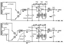
While I wait for a batch of new resistors, I thought about moving the last one in front of the regulator. I also changed the first filter order out of curiosity, so it now starts with a cap rather than resistor.
I do not know why but the voltage is even higher now, the DC starts at 410 instead of 390. The difference across the regulator is still above 125V, 132V now, used to be 130. The good news is that the 100Hz hum is super low. What is a bit worse now is the 50-150-250 series on the lowest gain.
I do not know why but the voltage is even higher now, the DC starts at 410 instead of 390. The difference across the regulator is still above 125V, 132V now, used to be 130. The good news is that the 100Hz hum is super low. What is a bit worse now is the 50-150-250 series on the lowest gain.
Attachments
Of corse, without the first resistor the capacitor is charged to the peak voltage of the sinewave from the transfo.After that you have basicaly an C-R-C-R-C filter and no stabilisation what so ever since the IC is bridged by conducting zeners.
Normaly those zeners are suposed not to conduct, they'r only there to prevent exessive voltage on the IC.
With the two resistors between first and second capacitor you have a sort of high-cut filter preventing HF-noise to pass.
Mona
Normaly those zeners are suposed not to conduct, they'r only there to prevent exessive voltage on the IC.
With the two resistors between first and second capacitor you have a sort of high-cut filter preventing HF-noise to pass.
Mona
> I guess next i should i flip
_I_ think you should ditch the TL783.
I've been following this puzzle on two forums. IMHO the TL783 is just not a good choice.
Since you have Zeners, use a few more on a MOSFET.
Or, if the current is so steady, just do C-R-C-R-C-R-C filter. Four 200uFd and three 2.5K will give a LOT of filtering. The tubes that follow generally do not care 240V or 280V of B+.
Attachments
Last edited:
While I wait for a batch of new resistors, I thought about moving the last one in front of the regulator. I also changed the first filter order out of curiosity, so it now starts with a cap rather than resistor.
I do not know why but the voltage is even higher now, the DC starts at 410 instead of 390. The difference across the regulator is still above 125V, 132V now, used to be 130. The good news is that the 100Hz hum is super low. What is a bit worse now is the 50-150-250 series on the lowest gain.
your post showsThank you. I made it like this because i saw more oftwn psu schematics show a cap first - i thought mine was atypical in the original version.
I guess next i should i flip the crcr to rcrc?
Thanks again
rCRCR
You don't need any more stages for a correctly working regulator. You already have three resistances as current limiters and have a cascaded pair of RC filters.
If you forego the regulator, then one or two more stages of filtering could be beneficial.
Last edited:
I hope to have more parts in tomorrow, next version will be:
rectifier (MUR1100 instead of 1N4007) 2K new single 470uF TL783 400uF(poly). That should be 350V at the regulator and if I still see voltage across the zeners I will put a new regulator and if still shaky will ditch it and go for the simple variant with 3 resistors 2K or 2K2 each...
rectifier (MUR1100 instead of 1N4007) 2K new single 470uF TL783 400uF(poly). That should be 350V at the regulator and if I still see voltage across the zeners I will put a new regulator and if still shaky will ditch it and go for the simple variant with 3 resistors 2K or 2K2 each...
- Status
- This old topic is closed. If you want to reopen this topic, contact a moderator using the "Report Post" button.
- Home
- Amplifiers
- Power Supplies
- Maddening ripple hum