Hi, I've been designing a simple regulated DC power supply for my headphone amplifier, which need 12-13V DC at a 500mA rating.
This I what I've come up with:
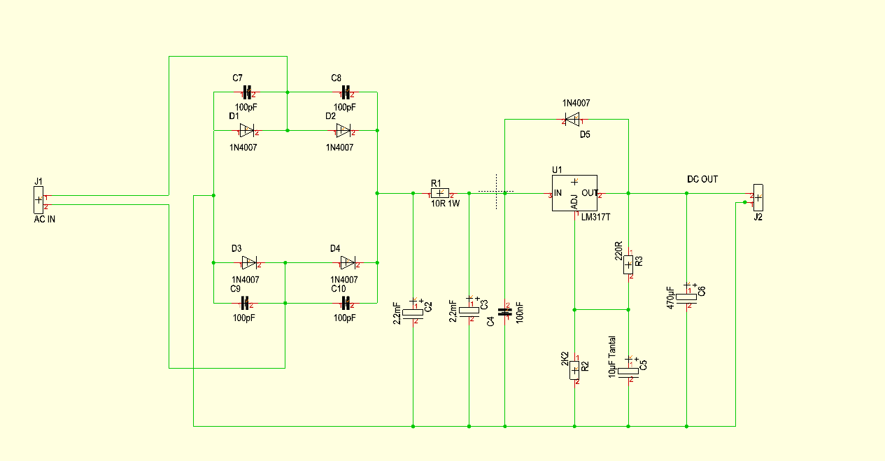
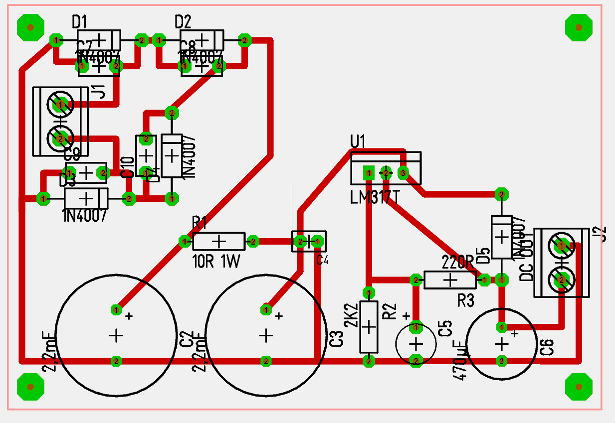
And this is the circuit layout:
I built the circuit and there is a problem.
From the output of the headphone amp I hear a loud 60Hz hum.
When I measure the output voltage of the PS circuit with a voltmeter, I get 0.150Volt AC. Where do you think the flaw is?
Please help, this thing is making me crazy.
This I what I've come up with:
And this is the circuit layout:
I built the circuit and there is a problem.
From the output of the headphone amp I hear a loud 60Hz hum.
When I measure the output voltage of the PS circuit with a voltmeter, I get 0.150Volt AC. Where do you think the flaw is?
Please help, this thing is making me crazy.
From the output of the headphone amp I hear a loud 60Hz hum. When I measure
the output voltage of the PS circuit with a voltmeter, I get 0.150Volt AC.
Looks ok. Are all the capacitors installed with the right polarity?
With your dvm set on DC Volts what is the reading of the supply voltage input,
and also the supply voltage output?
If the amplifier is powered from a battery or other supply, is the hum gone?
Last edited:
Thank for the reply rayma ")
Yes, I've just checked the capacitors and they installed right.
I read 0VDC at the input and 13.6VDC at the output.
When I connect the Power supply to a load (the headphone amp), the output voltage drops down to approximately 9V.
The hum is totally absent when I run the headamp from a battery.
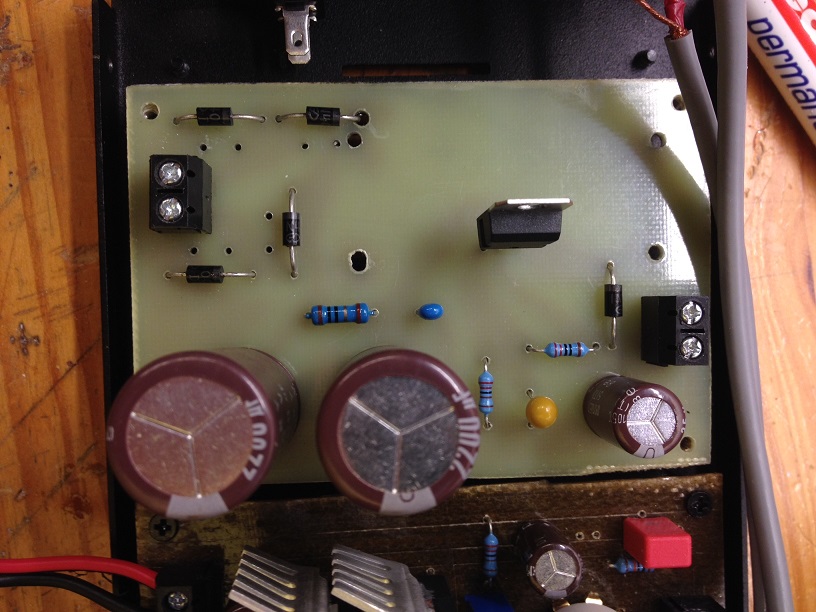
EDIT: this is a photo of the circuit.
Yes, I've just checked the capacitors and they installed right.
I read 0VDC at the input and 13.6VDC at the output.
When I connect the Power supply to a load (the headphone amp), the output voltage drops down to approximately 9V.
The hum is totally absent when I run the headamp from a battery.
EDIT: this is a photo of the circuit.
Last edited:
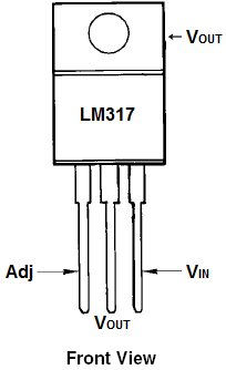
lm317.......wrong pin layout/connection?
adj. is the mid of the three legs i think..........
No, I seem to have gotten that right...
I read 0VDC at the input and 13.6VDC at the output. When I connect the Power supply
to a load (the headphone amp), the output voltage drops down to approximately 9V.
How is the supply input at 0VDC when there is 13VDC output? That can't be right.
Are you sure the diode across the regulator is connected cathode to input and
anode to output? If it were reversed, the regulator would be "shorted out" and not function.
Sorry rayma, I misunderstood.
The DC voltage at the input pin of the LM317 is approximately 17.5V.
Yes, I'm sure about the diode too.
Then the regulator is dropping out of regulation under load (hence the hum).
Check the input resistor between the capacitors, it's too high in value
and should be more like 1R. The 500mA load would drop 5VDC across 10R,
and cause the regulator to drop out.
Solder a 1R (1W) across the 10R and see if the output now stays high under load.
The 1R will still filter well enough with the large cap after it, but will only drop
0.5V under load.
Last edited:
Resistor R1 checks out as 10Ohm.
If the regulator is dropping out of regulation under load, may choosing a lower output voltage help? Let's say 11.48V, which would mean 1k8 instead of 2k2 for R2.
It's strange however that I detect an AC voltage at the output of the regulator even when it's not under load and it's still regulating well... How would you explain it?
Resistor R1 checks out as 10Ohm.
If the regulator is dropping out of regulation under load, may choosing a lower
output voltage help? It's strange however that I detect an AC voltage at the output
of the regulator even when it's not under load and it's still regulating well.
You'll need to lower the 10R value substantially, due to the 500mA load requirement.
The hum under no-load conditions is a bit of a mystery right now.
If the regulator is dropping out of regulation under load, may choosing a lower output voltage help?
You'll also need a heat sink on the TO-220 regulator package, to handle the 500mA current
and 5VDC drop (2.5W). Fortunately, there is room on the board.
Last edited:
Problem solved.
What I did was:
1. changing R1 from 10Ohm to 1Ohm
2. changing R2 from 2k2 to 1k8, thus reducing the output voltage from 13.75V to 11.48V
I left the space (and made the four big holes) by purpose. This is how it looks with the heatsink:

It's rated at 12VAC - 1Ampere.
Which is probably where all my problems came from. If used a 15VAC transformer, I think everything would have worked....
What puzzled me is that before this circuit I did an almost identical one, which was based on a fixed-voltage LM2940CT-12 voltage regulator. R1 was 10Ohm and everything worked!
I then decided to make a new circuit (this one) based on the LM317T regulator because of its lower noise specifications. Now the hiss I was experiencing with LM2940 is almost gone. It was really annoying.
Do you think I would obtain a better result (as far as noise is concerned) by replacing C5, which is now 10uF, with a higher value? I have a 47uF tantal at hand, that's why I'm asking.
Thanks for the help so far!!!!!!
What I did was:
1. changing R1 from 10Ohm to 1Ohm
2. changing R2 from 2k2 to 1k8, thus reducing the output voltage from 13.75V to 11.48V
You'll also need a heat sink on the TO-220 regulator package, to handle the 500mA current and 5VDC drop (2.5W). Fortunately, there is room on the board.
I left the space (and made the four big holes) by purpose. This is how it looks with the heatsink:
what transformer do you use ? (VA-rating?)
It's rated at 12VAC - 1Ampere.
Which is probably where all my problems came from. If used a 15VAC transformer, I think everything would have worked....
What puzzled me is that before this circuit I did an almost identical one, which was based on a fixed-voltage LM2940CT-12 voltage regulator. R1 was 10Ohm and everything worked!
I then decided to make a new circuit (this one) based on the LM317T regulator because of its lower noise specifications. Now the hiss I was experiencing with LM2940 is almost gone. It was really annoying.
Do you think I would obtain a better result (as far as noise is concerned) by replacing C5, which is now 10uF, with a higher value? I have a 47uF tantal at hand, that's why I'm asking.
Thanks for the help so far!!!!!!
Do you think I would obtain a better result (as far as noise is concerned) by replacing C5,
which is now 10uF, with a higher value? I have a 47uF tantal at hand
That can help with noise. It may then be advisable to add a second discharge diode
in "antiparallel" to R3 so the large capacitor will discharge quickly at turn off.
Normally the extra diode would be reversed biased, and off.
- Status
- This old topic is closed. If you want to reopen this topic, contact a moderator using the "Report Post" button.
- Home
- Amplifiers
- Power Supplies
- Help needed with a regulated power supply