Building a tube microphone project, schematic had 9VAC and a LM317 regulator for the 6.3VDC heater. Since I hate hot regs that have to burn down lot, I bought a 6.3VAC trafo. Used 1N4007 diodes, I forgot they waste about 2V (I'm a noob) and the regulator seems to need some 2V Vin-Vout difference to work well. As a result I only get 5.6VDC output under load.
My usual supplier has 11DQ10 Schottky diodes, can I hope that these will really waste less voltage? If it ends up at 6.1 I'm happy. Are these diodes OK for tube projects? Yeah I think the last one is a silly question but oh well.
Thanks!!
My usual supplier has 11DQ10 Schottky diodes, can I hope that these will really waste less voltage? If it ends up at 6.1 I'm happy. Are these diodes OK for tube projects? Yeah I think the last one is a silly question but oh well.
Thanks!!
the regulator seems to need some 2V Vin-Vout difference to work well.
As a result I only get 5.6VDC output under load.
The regulator is not working. Use a voltage doubler circuit, because you need to have
extra input voltage for line variation, etc. http://hyperphysics.phyastr.gsu.edu/hbase/electronic/ietron2/voldoub.gif
Or you can use a suitable DC-DC converter. http://www.ebay.com/itm/2A-DC-DC-bo...4v-/331973393414?_trksid=p2141725.m3641.l6368
Last edited:
I found I could get away with AC heater voltages if I was careful with circuit layout.
Keep transformers away from valves and audio signals.
Keep heater wires away from audio signals.
If using a pcb use plenty of copper pours connected to zero volts.
The only time I used DC heater volts was on a audio mixer and after I turned the mixer on it had hum due to not following previous comments.
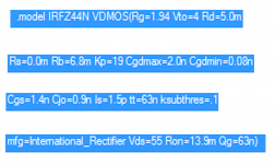
Elvee, the default LTSPICE model of the IFZ44N MOSFET has infinite output resistance; its "Early Voltage" is infinity; its gds=0. This is because the model does not include a value for the SPICE parameter "LAMBDA", so it gets LAMBDA=0, which means the I-V curves are perfectly flat at large VDS. Infinite output resistance. See image below.
This is important in your circuit because rds provides a circuit pathway for input ripple to disturb the output. In effect vout/vrippleIn is determined by a voltage divider: (rds) from input to output, and (the output impedance of M1) from output to AC ground. The default LTSPICE model sets rds=Infinity which is unrealistic, so the simulated Line Rejection is also unrealistic.
Looking down the page at other LTSPICE models of other Nchannel MOSFETs, it seems that LAMBDA=0.09 is a more typical value. In the saturation region, the LTSPICE model equations have dIds/dVds = LAMBDA. In other words, gds = LAMBDA.
So I think it would be more realistic to set LAMBDA=0.09 in the SPICE model. (You could also achieve the same thing by connecting an 0.09 Siemens conductance from drain to source, in series with a 5 millifarad capacitor for DC blocking+AC coupling). Simulated Line Rejection may still be good; or it may not. But at least the MOSFET will be more realistically modeled.
_
Attachments
Sure, most of the MOS models are targeted towards switching applications and disregard practically everything else (even bipolars intended for linear applications have seriously questionable parameters), but here, what counts is a sufficiently low Rdson at a reasonable Vgs, and any device satisfying this condition will work properly in this application.Elvee, the default LTSPICE model of the IFZ44N MOSFET has infinite output resistance; its "Early Voltage" is infinity; its gds=0. This is because the model does not include a value for the SPICE parameter "LAMBDA", so it gets LAMBDA=0, which means the I-V curves are perfectly flat at large VDS. Infinite output resistance. See image below.
Some may end with 50mV of ripple and others with 500µV, but this will make no practical difference (except for true audiophiles, of course)
Attachments
- Status
- This old topic is closed. If you want to reopen this topic, contact a moderator using the "Report Post" button.
- Home
- Amplifiers
- Power Supplies
- 6.3VAC to 6.3VDC with LM317